First of all, a few important notes that you should definitely pay attention to.
https://www.segeln-forum.de/thread/74840-lora-monitoring-und-alarmserver/
https://github.com/norbert-walter/LoRa-Boat-Monitor
The LoRa boat monitor is used to monitor the boat when you are away. Various measured values are transmitted continuously at freely adjustable time intervals via LoRa radio technology (long range) to the LoRaWAN forwarded and recorded. The data is sent from the TTN server V3 (The Thinks Network) received and cached in Ireland for Europe and then to Ubidots forwarded as a web frontend. The data transmission is secured by encryption up to Ubidots. The measured data is displayed in Ubidots and various notifications can be sent by email when measured values are exceeded. There are a large number of LoRa gateways which can receive the sent measurement data and forward it to the TTN server. Many LoRa gateways are operated non-profit by private individuals. Anyone who wants to can operate their own gateway and make it available to the general public. In Europe, the radio technology uses the license-free frequency range around 868 MHz and uses a special transmission technique (chirp) to achieve large ranges of up to 50 km at low data rates. The ranges depend on the type of transmission, the antenna height and the environment. Typical ranges of 1…4 km are possible in built-up areas such as cities. In open environments such as lakes and the sea, up to 50km can be achieved. There are no costs for data transmission when sending LoRa telegrams. LoRa devices can be used in the same way as cell phones. The LoRa data is received and forwarded by any public gateway without prior registration. If the device is registered with TTN, the data can be picked up or forwarded from there. This is the big difference to other long range transmission techniques like SIGFOX and mobile data networks such as NB IoT over 3G/4G/5G. If there is no LoRa gateway in range, a simple 1-channel or 3-channel LoRa gateway can be set up with the same board. Only a few components are then omitted and a gateway firmware is used. Alternatively, the measured values can also be sent directly to Ubidots via WLAN, provided that a WLAN is within range.
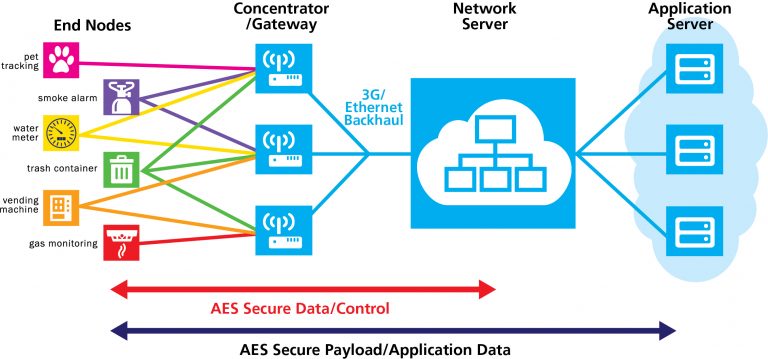
Image: LoRa data transmission (Semtech GmbH)
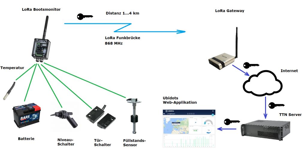
Image: Functional overview LoRa boat monitor
The LoRa boat monitor has the following functions:
- 10… 32V supply voltage
- 1.2W power consumption
- Protection class IP68, waterproof
- LoRa transmitter and receiver with OLED display
- 868 MHz, SF7… SF12, 100 mW transmission power
- LoRa registration via ABP
- Dynamic spreading factor adjustable SF7…FS10
- Supports channels 0… 7 dynamic and fixed
- Data transfer rate: 0.3 to 50 kbit / s
- Max. telegram length for user data: 200 bytes (40 bytes currently used)
- Range: built-up area 1… 4km, open area up to 50km
- LoRa transmission interval 30s… 2.1h
- One-channel, three-channel and eight-channel modes can be set
- Feeding the data into The Thinks Network (TTN V3)
- Parameterization of the LoRa boat monitor possible via return channel (channel, SF, transmission interval, relay)
- WLAN (2.4 GHz) for alternative data transmission
- Web interface for operation
- Firmware update possible via WLAN and Internet
- GPS sensor for geographic location coordinates
- BME280 for measuring temperature, humidity and air pressure
- Victron devices with VE.Direct (receive and transmit) such as battery monitor or solar charger
- 1x battery voltage measurement (0… 32V service battery)
- 1x potential-free alarm contact eg for bilge and door monitoring
- 2x tank sensors (0 ... 180 Ohm) with percentage display
- Calibratable tank and voltage sensors
- 1x relay output for potential-free switching of loads with time specification (5min...21h) up to 3A (12V or 230V)
- 2x 1Wire connection for temperature sensors DS18B20 for battery monitoring and refrigerator
- Monitoring and alerting via Ubidots web frontend or Grafana
- Output of sensor data as NMEA0183 telegrams (also data from VE.direct)
- Alert via email when limit values are exceeded via Ubidots or Grafana
- Automatic data storage for the last 31 days on Ubidots and for 1 year on the OBP database
- Use of cheap embedded modules
- No SMD components on the board
- Board can be ordered here: https://aisler.net/p/GEIYWWXZ
- Android app: LoRa_Boatmonitor_1.apk
Table of contents
- 1 sensors and connectivity
- 2 assembly of the circuit board
- 3 Flashing the firmware
- 4 Display of measured values in the web front end
- 5 Display of measured values in the OLED display
- 6 Registration in the LoRa network TTN V3
- 7 LoRa access data and operating modes of the boat monitor
- 8 Data visualization on the Internet
- 9 Output of NMEA0183 sensor data via WiFi
- 10 Practical tips
- 11 questions and answers
- 12 testimonials
- 13 pictures
sensors and connectivity
Various sensors and actuators can be connected to the LoRa boat monitor via the terminal strip. The following sensors are supported:
- battery voltage sensor
- environmental sensor
- Victron VE.Direct (receive, send)
- GPS sensor
- alarm contacts
- level sensors
- temperature sensors
battery voltage sensor
The battery voltage sensor is already built into the LoRa boat monitor. The battery voltage can be monitored via the supply voltage connection. To do this, the ESP32 measures the battery voltage at an analog input. Battery currents or power cannot be measured. It is only possible to measure the battery voltage. The measuring accuracy of the battery voltage is approx. 0.1V.
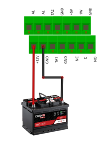
Fig.: On-board battery connection
For the best possible measurement results, the battery voltage sensor should be calibrated. When the firmware is delivered, standard values are stored that are more inaccurate.
environmental sensor
A BME280 module is installed on the circuit board of the LoRa boat monitor as an environmental sensor. The sensor can measure air temperature, humidity and air pressure. The local altitude is also determined via the air pressure and the dew point is calculated via the air humidity and the temperature as secondary variables. However, one should not have too high expectations of the measuring accuracy of the sensor. Almost 98% of all BME280 boards sold are plagiarisms that have significantly poorer measurement accuracy than the original Bosch sensor. This is particularly noticeable when measuring the air pressure. The values vary greatly. The temperature sensor often shows temperatures that are far too high due to the chip heating up itself. Accordingly, the calculation of the dew point is also quite imprecise.
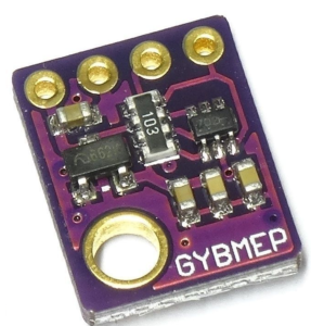
Fig.: BME280
Victron VE.Direct
The VE.Direct interface from Victron is supported from firmware version V1.04 and can read battery monitors, solar chargers and inverters. In order to be able to use the VE.Direct interface, the pins of the environmental sensor BME280 are used. The BME280 cannot then be used at the same time and must be removed. A connector for VE.Direct is connected in its place.
| Pin BME280 | Signal VE Direct |
Pin VE.Direct |
Wire color VE.Direct |
| VIN | 3.3V | 4 |
yellow |
| GND | GND | 1 |
black |
| SCL | TX | 3 |
White |
| SDA | RX | 2 |
red |
Tab.: Pin assignment
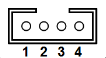
Fig.: VE.Direct device connector (JST 2mm, 4-pin, top view)
Danger! Only 3.3V TTL signals are allowed on the LoRa boat monitor. Some Victron devices also work with 5V TTL signals. These devices can only be used with an upstream voltage divider. For data transmission between the VE.Direct device and the LoRa boot monitor, the TX and RX lines must be connected to the opposite side to enable transmission. Commercial cables from Victron are prepared accordingly and can be used.
Usable Victron devices with VE.Direkt interface:
| device type | Model | signal level | comment |
| battery monitor | BMV-700, BMV-700H, BMV-702, BMV-710H, BMV-712 smart* | 3.3V TTL | |
| 230V inverters | Phoenix Inverter 250, 375, 500VA | 5.0V TTL | voltage divider required |
| solar chargers | Blue Solar MPPT 75/10…150/100 | 5.0V TTL | voltage divider required |
Table: Usable VE.Direkt devices
* tested device
VE.Direct can be read by Victron devices as well as read by the LoRa boat monitor. The LoRa boat monitor presents itself as BMV-712 smart and can output the following information:
- battery voltage
- battery temperature
- alarm condition
- relay state
All unused values from the BMV-712 smart are output with zero values. Under Device Settings in the web configuration can be found under Env Sensor the VE.Direct operating mode can be selected.
If a device with a VE.Direct interface can be read, some measured values can also be transmitted via NMEA0183 as an XDR telegram via WiFi and evaluated and displayed in SignalK, for example.
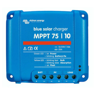
Fig.: Victron solar charger with VE.Direct (Victron)
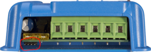
Fig.: VE.Direct Port bottom left 4 pins (Victron)
It is intended that battery monitors, solar chargers and other devices with VE.Direct are supported on the VE.Direct interface. However, only one device can be used on the VE.Direkt interface. Some of the device values are also transmitted via LoRaWAN and NMEA0183.
GPS sensor
A sensitive GPS receiver is installed in the LoRa boat monitor for location detection, which can record the geographical position of the boat very precisely. It even works below deck if the sensor doesn't have a direct view of the sky. Depending on the installation position of the boat monitor, the GPS module can be soldered lying or standing on the circuit board. This should help ensure that the GPS antenna integrated in the module can always be aligned parallel to the water surface, so that the antenna always points towards the sky. In difficult reception situations, such as in a steel boat, an external GPS antenna can also be used. The integrated antenna can be separated via a plug, to which an external antenna can also be connected. There are pigtail cables in specialist shops to get from the small circuit board connectors to larger SMA coaxial connectors.
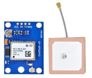
Fig.: GPS receiver
alarm contacts
Potential-free alarm contacts can be connected to the LoRa boat monitor. Typically, these are simple mechanical switches that connect two contacts together. An input for alarm contacts is provided on the boat monitor. In the Ubidots frontend it can be specified whether the alarm contact should act as an opener or closer.
However, several contacts can be connected to the input of the alarm contact. In this way, several points can be monitored at the same time, such as the bilge water in the foredeck, in the saloon and in the stern. Basically you can only use several sensors of the same switch type, opener or closer, at the alarm input. If breakers are used that open the contact when triggered, all sensors are connected in series. If, on the other hand, closers are used, all sensors are connected in parallel.
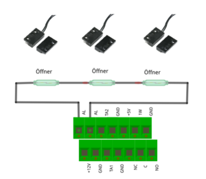
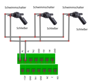
Fig.: NC in series, NO in parallel
A mixed operation of different types of alarm contacts is also possible, for example, provided they use the same type of switch. For example, you could use door contacts for intrusion detection and bilge sensors at the same time. When the alarm is triggered, however, it is not possible to determine which type of alarm contact has triggered. It is then essential to check on site which triggering event it was.
Caution: Please note that the triggering of an alarm contact may be delayed via the LoRa boat monitor. As a rule, the information is transmitted within the set transmission interval. However, in difficult radio environments this can take significantly longer. Make sure beforehand how good the connection quality of the LoRa radio transmission is. For this purpose, the frequency of telegram inputs can be monitored.
level sensors
All sensors that function on the basis of a change in resistance can be used to monitor fill levels. Common sensors work in the range of 0...180 ohms or 0...200 ohms. All these sensors can be used on the LoRa boat monitor. To do this, the sensors are connected directly to the terminal strip with the two cables. A total of two inputs for level sensors are available.
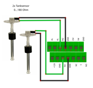
Fig.: Connection level sensors
Caution: Several level sensors must not be connected in parallel to the pair of terminals. Only one sensor per pair of clamps may be connected. Note that simple level sensors cannot output the level continuously and without jumps. In most cases, level sensors with magnetic floats only output the readings in 10% increments. The measured values remain between the steps until a new step has been skipped. This is particularly important in the case of low fill levels, where the fill level displayed does not have to correspond to the real fill level.
In order to be able to display the levels of any level sensors regardless of the tank geometry, it is possible to calibrate the sensors. A linear and a non-linear correction function are available for this purpose. The parameters of the correction function are determined by testing the tank by filling the tank by the liter step by step and assigning the measurement results to the fill levels. In this way, trapezoidal or any tank cross-sections can also be recorded correctly.
temperature sensors
1Wire temperature sensors can be used to monitor temperatures in the boat. To do this, the sensor is connected to the three contacts. Currently 2 sensors are supported, which can be placed in parallel. The inexpensive 1Wire temperature sensors can be purchased from retailers as a watertight encapsulated variant in a metal housing.
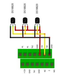
Fig.: Connection 1Wire temperature sensors DS18B20
sample application
An example is presented here as an idea of how to use the LoRa boat monitor. In the scenario, two level sensors are used, one for diesel and one for fresh water. The bilge is monitored with a float switch designed as a closer. If water collects in the bilge, a message can be sent by e-mail. With the two temperature sensors, the temperature of the on-board battery and the room temperature in the boat can be monitored. A 1 kW fan heater is connected to the normally open contact of the relay. The heater fan can be controlled remotely via the LoRa boat monitor. For this purpose, the relay can be switched on at a certain time. The relay automatically disconnects the circuit after a specified time. For example, you could keep the room temperature in the boat above the freezing point or above the dew point. This can prevent frost or mold growth.
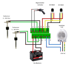
Fig.: Example circuit
assembly of the circuit board
A circuit board for the LoRa boat monitor can be purchased at Aisler be ordered. All the necessary production data is stored and ordering is extremely easy. The circuit board is populated on two sides with push-through components. If you have some soldering experience, the assembly should not cause any problems. It is best to start with the back of the board first. All flat components are located there. Then equip the front with all the large components and modules. For the Heltec LoRa ESP32 module (Q1) use socket strips and do not solder the module directly. The initial programming via the USB socket sometimes causes problems and the module has to be removed from the socket strips in order to be able to program it successfully. Subsequent software updates can be carried out easily in the web interface. The module does not have to be removed for this.
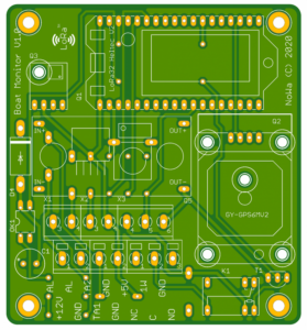
Fig. Circuit board
Depending on how you want to install the housing of the LoRa boat monitor, the GPS module can be installed in different ways, either horizontally or vertically. It should be installed in such a way that the metallic surface of the GPS antenna points horizontally to the sky. This way you get an optimal reception performance. The modules for the GPS sensor and the BMP280 contain mounting holes. Use plastic spacer bolts to fasten the modules and then solder in the modules. In this way you avoid inadmissible force effects on the soldering pins.
For circuit board assembly you can use the interactive component and assembly list use. There you will find a component list with the corresponding component sizes and their position on the circuit board. The LoRa boat monitor schematic is deposited on GitHub.
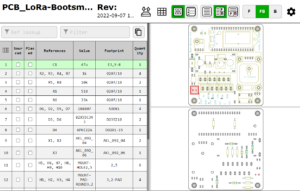
Fig.: Interactive component and placement aid
When soldering, make sure the solder joints are clean and remove solder residue from the circuit board before installing the circuit board in the housing.
Before inserting the Heltec LoRa ESP32 module into the socket strip, you must set the output voltage of the DC/DC converter (Out+, Out-) to 5.7V with the small adjusting screw on the blue potentiometer. When delivered, the potentiometer is in any position and can output too high a voltage and destroy the Heltec module.
Flashing the firmware
When the Heltec LoRa ESP32 module is delivered, there is test firmware on the module that must be replaced with the firmware of the LoRa boat monitor. To flash the firmware, take the module out of the socket strip and connect it to the PC or laptop with a USB cable and go to the following website with a Chrome or Edge web browser and use it Web Flash tool. After selecting the serial USB interface used, the Heltec module is deleted and the firmware is then transferred. If the Web Flash Tool is used under Windows, the appropriate drivers for the serial/USB converter must be installed. You can find the links to the drivers in the Web Flash Tool. All drivers are already available under Linux.
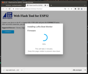
Fig. Web Flash Tool
After the flash process, it is possible to switch to the serial console. A series of debug information is output there and the functionality can be checked.
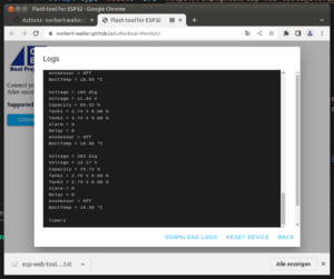
Fig.: Serial console
Display of measured values in the web front end
To display the current measured values, a small web server is integrated into the LoRa boat monitor, via whose websites the measured values and some operating parameters can be set and displayed. To do this, you connect via the WiFi network NoWa with the password 12345678 and then calls the website http://192.168.4.1 on.
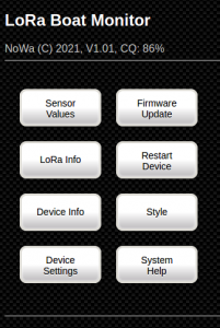
Fig .: Main menu
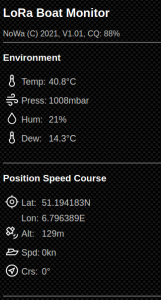
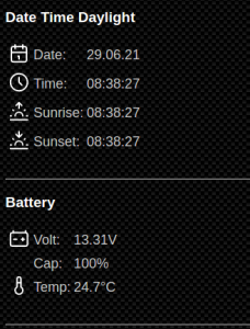
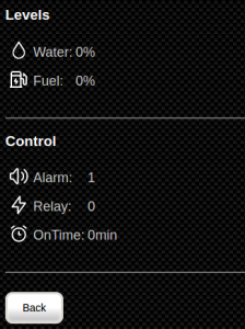
Fig.: Sensor Info
Display of measured values in the OLED display
The most important measured values of the LoRa boat monitor are also shown on the OLED display and are continuously updated.
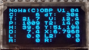
Fig.: OLED display
The meaning of the displayed values is as follows:
| abbreviation | meaning | abbreviation | meaning |
| C | LoRa telegram counter | dT | time interval in s |
| T | Air temperature in °C | V | Battery voltage in V |
| P | air pressure in mbar | T2 | 1Wire temperature sensor in °C |
| H | Humidity in % | X | GPS latitude |
| D | Dew point in °C | Y | GPS longitude |
| L | Tank sensor 1 | L2 | Tank sensor 2 |
| A. | alarm input | R | relay status |
Tab.: Display values in the OLED display
Registration in the LoRa network TTN V3
Before the LoRa boot monitor can send data to the TTN V3 network, the device must be registered there. A unique device ID, a network key and an application key are assigned for the boat monitor. The device ID is identical to the IMEI on a mobile phone and is used for identification. The network key is used to secure the transport route via radio and Internet. The application key is used to decrypt the data on the application level. The application level is the point at which the data is again unencrypted and processed. Theoretically, a LoRa device can also deliver the data for different independent applications at the same time. The boat's GPS data could, for example, be used in an application for display on a private map and displayed in another application for traffic flow display of all devices in a public map. Hence the additional encryption at the application level.
In order for data to be processed in the LoRa TTN V3 network, an application must first be created. The device is then assigned to the application and a payload decoder is also entered. How this configuration works in detail can here to be checked.
LoRa access data and operating modes of the boat monitor
Next we need to set the LoRa boot monitor to LoRa mode and enter the generated keys (see Registration in the LoRa network TTN V3). To do this, we connect to the WiFi network NoWa with the password 12345678, go to the website http://192.168.4.1 and go to the page Device Settings.
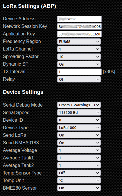
Fig.: Device Settings
Under Device Address, Network Session Key and application key the values are entered that were generated on the TTN page and that we printed out. Caution: The device address must not be confused with the device EUI, otherwise the LoRa network access will not work. Please ensure that you completely delete the input fields beforehand. The display fields hide part of the input values that continue to the right. as frequency region got to EU868 to be chosen. Above LoRa Channel can be set on which channels the LoRa boat monitor should send. The following options are available:
- 0…7
- 0…3dynamics
- 0…7 dynamics
If only one channel is selected, the boat monitor transmits permanently on this one channel. With dynamic channel selection, the channels are switched one after the other after each transmission. For public LoRa gateways should 0…7 dynamics to get voted. For older single-channel gateways, the channel 1 or higher to choose. Channel 0 should not be used with one-channel gateways, since this data is not accepted in the TTN network.
The spreading factor (SF) indicates with which frequency spread should be worked. The frequency spread also called chirp is called, serves to distribute the useful signal over a larger frequency band. This reduces sensitivity to interference and improves data transmission. The higher the frequency spread, the more securely data can be transmitted. On the other hand, the possible data rate of the information to be transmitted decreases. Spreading factors between 7...10 can be set. Smaller values use less spread spectrum and can transfer data faster. However, the range is not very high. In built-up areas such as cities, ranges of 1…4 km are achieved. If the data transmission is disrupted, you can try higher spreading factors. With SF10, ranges of up to 60 km can be achieved in open terrain such as water.
With DynamicSF dynamic frequency spreading is possible. If it is switched on, several spreading factors are continuously used during transmission. The transmission scheme consists of 10 time slots in which data is transmitted. The transmission scheme is repeated continuously.
| spreading factor | timeslot 1 | Timeslot 2 | Timeslot 3 | Timeslot 4 | Timeslot 5 | Timeslot 6 | Timeslot 7 | Timeslot 8 | Timeslot 9 | Timeslot 10 |
| SF7 fixed | SF7 | SF7 | SF7 | SF7 | SF7 | SF7 | SF7 | SF7 | SF7 | SF7 |
| SF8 fixed | SF8 | SF8 | SF8 | SF8 | SF8 | SF8 | SF8 | SF8 | SF8 | SF8 |
| SF9 fixed | SF9 | SF9 | SF9 | SF9 | SF9 | SF9 | SF9 | SF9 | SF9 | SF9 |
| SF10 fixed | SF10 | SF10 | SF10 | SF10 | SF10 | SF10 | SF10 | SF10 | SF10 | SF10 |
| SF7 dynamic | SF7 | SF7 | SF7 | SF7 | SF7 | SF7 | SF7 | SF7 | SF8 | SF9 |
| SF8 dynamic | SF8 | SF8 | SF8 | SF8 | SF8 | SF8 | SF8 | SF8 | SF9 | SF10 |
| SF9 dynamic | SF9 | SF9 | SF9 | SF9 | SF9 | SF9 | SF9 | SF9 | SF10 | SF11 |
| SF10 dynamic | SF10 | SF10 | SF10 | SF10 | SF10 | SF10 | SF10 | SF10 | SF11 | SF12 |
Tab.: LoRa transmission scheme
The greatest ranges are achieved with SF9 dyn and SF10 dyn. With these settings there are also the SF11 and SF12. These speeding factors must not be used continuously and are only used in the dynamic operating modes.
With TX Interval the frequency of the LoRa telegram transmissions can be set as a multiple of 30s. Transmissions shorter than 30s are not permitted according to the LoRa specification. In real operation, transmission intervals of 10...15 minutes are sufficient. Then 4…6 LoRa telegrams are sent per hour.
Attention: It should be noted, however, that the alarm response time of the LoRa Boost Monitor is directly related to the transmission interval. If you need fast alarm response times, you have to use short transmission intervals.
Data visualization on the Internet
The data can be visualized online in various ways via the Internet. There are 3 frontend systems with different functionality available:
-
Grafana service by Open Boat Projects
-

- Registration: not required
- Unlimited transfer of values
- Unlimited retrieval of values
- Display: Values, diagrams, location on map
- Own dashboard design: Yes, after mail registration
- Data storage 1 year
- Alert notifications via Mail, Slack and OnCall
- Free service
- Demo test page (login: guest/loragast)
-
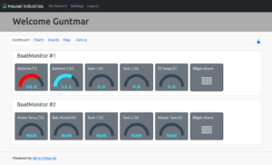
Maritime Data Servers by Guntmar Hoche
-
- Registration: required
- Unlimited transfer of values
- Unlimited retrieval of values
- Display: Values, diagrams, location on map
- Custom Dashboard Design: Yes
- Data storage unlimited
- Alarm notifications via Mail and Telegram
- Free service
- Demo test page (Log in: test@test.de/test)
-
Ubidot's Stem (Free Version) by Ubidots
-
- Registration: required
- Up to 10 devices. First 3 devices free, then $ 4.5 / device / month
- Up to 10 variables per device
- Up to 1 plugin with 10,000 plugin executions per month
- Ingest 4,000 data points per day across all your devices
- Retrieve 500,000 data points per day across your entire account
- Data rate with one request per second across all your devices
- Display: Values, diagrams, location on map
- Custom Dashboard Design: Yes
- Data storage 1 month
- Up to 3 dashboards with up to 10 widgets each
- Alert notifications via email
- Free service
- Pay models with more functionality can be booked
In order to be able to display the data, appropriate configurations must be made both in the LoRa TTN network for data forwarding and further configurations in the respective front ends. To do this, follow the respective links in the headings.
Output of NMEA0183 sensor data via WiFi
The sensor data of the LoRa boat monitor can also be transmitted as NMEA0183 sentences via WiFi. 3 telegrams are generated for this. A telegram is the copy of the RMC telegram from the GPS sensor. Further telegrams from the GPS sensor are not transmitted. The measurement data is transmitted in two further XDR telegrams. The XDR telegrams are divided into measurement data from the environmental sensor and other measurement data. The NMEA0183 telegrams are transmitted once per second. However, the data of the RMC telegram is only renewed every 5s and is not particularly suitable for navigation. In the foreground is the location of the boat and not the navigation with this signal.
The NMEA0183 data can be retrieved from the LoRa boat monitor over TCP on port 6666. Only one device can be connected to the port at a time. Depending on whether data is read from the VE.Direct interface or not, these are also sent. The different XDR telegrams are listed below.
VE.Direct reception active:
$IIXDR,V,14.04,V,BVolt,C,-0.10,C,BTemp,I,0.00,A,BCur,P,0.00,W,BPow,P,408.00,P,BCap*5f
$IIXDR,L,0.00,P,Water,L,0.00,P,Fuel,I,0,B,Alarm,O,0,B,Relay*37
$GPRMC,175017.00,A,5111.64541,N,00647.81891,E,0.468,,050323,,,A*72
VE.Direct reception inactive:
$IIXDR,V,12.14,V,BVolt,C,19.37,C,BTempP,74.45,P,BCap,*75
$IIXDR,L,0.00,P,Water,L,0.00,P,Fuel,I,0,B,Alarm,O,0,B,Relay*37
$GPRMC,173714.00,A,5111.64607,N,00647.81899,E,0.724,,050323,,,A*72
Practical tips
antenna position
In order to achieve an optimal transmission range, the antenna should be mounted as high as possible. This prevents the transmission signal from being shadowed by the surrounding buildings. An antenna position at the top of the mast or on the spreader would be ideal.
Electrical connection
The LoRa boat monitor should be connected to the 12V on-board network via a fuse. The LoRa could, for example, practice its own switching on the switch panel. It can be switched on or off as required.
Installation
First put the LoRa boat monitor into operation in an environment where reliable signal reception is possible. For example, this is the case in most cities. Make sure on TTNMapperthat there are LoRa gateways in your area. First try establishing a connection with a spreading factor of SF10. This will give the best results and should get you connected to a gateway. Then set up your dashboard in Ubidots as you need it and test the structure for a few days. Also test the message forwarding via e-mail. If the reception conditions are good, you can try to gradually reduce the spreading factor. If the boat monitor runs as desired, you can carry out the installation in the boat. Depending on the installation position of the boat monitor, the installation position of the GPS module can be changed if necessary. The metallic surface of the GPS antenna should point towards the sky. If the GPS reception conditions are poor, an external GPS antenna can be used.
questions and answers
How far can the LoRa boat monitor transmit the data?
There is no general answer to this question, as the range depends on a number of factors. In built-up areas, SF10 can reach gateways within a radius of 2…4 km. In free environments such as lakes or the open sea, it can be up to 60 km. How well LoRa signals can be received also depends on the number of gateways in the area, the distance and their antenna height. Many gateways are indoor gateways with a short range of less than 1 km. The few powerful gateways often have a high antenna position of more than 15 m. Look for such gateways in your area and determine the distance to your location. You can find this information in TTNMapper. You have a good chance of receiving your data if there are powerful gateways within a radius of around 10 km.
How often can the data be transferred?
The measurement data of the LoRa boat monitor can be transmitted every 5 min if the data is to be displayed in Ubidots. Higher data transfers generate a data volume that reaches the limits of the Ubidots free account and prevents the data from being displayed. If you want to use your own frontends, you can increase the sending rate to 30s. According to the LoRa specification, times less than 30s are not permitted and cannot be set.
How much data can I transfer?
The amount of data that can be transmitted over the LoRaWAN network is very limited. A maximum of 200 bytes can be transmitted per LoRa telegram. LoRa technology is a data transmission medium for a small amount of data that has low priority.
Is the LoRa boat monitor real-time capable?
Due to the limited amount of data and the long transmission intervals, the LoRa boat monitor is not real-time capable. The data can only be transmitted and processed as fast as the sending rate allows. In the standard application, this means a response time of up to 5 minutes. Typically, 80% of all telegrams are transmitted within the transmission interval. A fire alarm cannot be implemented with this.
What happens if LoRa data packets are lost?
Lost data packets are permanently lost and will not be resent. LoRa data transmission is not protected against data loss. You must expect that approx. 20…30% of the telegrams will be lost.
Is my data protected against unauthorized access?
The LoRa data transmitted by radio is encrypted end-to-end from the sensor to the backend to the frontend. Data received by radio is worthless to strangers because it cannot be decrypted.
How can I improve my data transfer?
To improve data transmission, you can increase the Spreading Factor (SF) and send the data more often. For best results, use a good antenna in a high position. Antenna positions at the end of the mast or in the spreader are optimal.
What circumstances make data transfer difficult?
If the LoRa boat monitor is in a metal boat, then the LoRa antenna must be mounted outside the boat. It may happen that the LoRa data packets are disrupted if other devices are also transmitting in the frequency range around 868 MHz, because this frequency range is license-free and can also be used by other services. Thanks to the frequency spreading process, LoRa radio technology is very robust against interference. Disturbances of the frequency band are noticeable through increased packet losses. The use of unsuitable antennas can also lead to reduced transmission ranges. In particular, the easily manufactured and supplied LoRa antennas for the LoRa Heltec board are unsuitable for permanent operation. They should be exchanged for matching antennas. In some cases, incorrectly equipped LoRa Heltec boards were also on the market, where the HF circuit part was designed for 433 MHz instead of 868 MHz. These LoRa Heltec boards suffer extremely from a lack of transmission range.
Are there alternatives to the free LoRaWAN community network?
In addition to the free LoRaWAN community network, there are also commercial LoRaWAN networks operated by larger mobile phone companies. However, there are costs for the data transmission, which can vary depending on the provider. In principle, the LoRa boot monitor can also be used in commercial LoRaWAN networks, provided the service provider supports ABP as a registration process. However, there is no experience yet.
There is no LoRa gateway in my port, what can I do?
If you do not have a LoRa gateway in your port and cannot reach a public LoRa gateway, you can operate a public gateway yourself. Ask your marina operator if you are allowed to operate a public LoRa gateway in the port. You need a power connection and internet access to operate. In this way, other sailors and the port operator can also benefit from it. If you want, you can also build a LoRa gateway yourself by using a reduced hardware variant of the LoRa boat monitor and with a LoRa gateway software operate. To contact us if you need help.
What are the costs for using the LoRa boat monitor?
Use of the LoRaWAN community network is free. The boat monitor only consumes 1.2W of power. With a 12V/100Ah on-board battery, the LoRa boat monitor can be operated for up to 500 hours until the battery is discharged to 50%. This corresponds to approximately 22 days of continuous usage time. It is therefore advisable to operate the LoRa boat monitor with shore power. There are costs for the shore power connection alone, but they are very low. That's about 6.5 kWh over a 6-month winter break. In the future there will be a sleep mode, with which the boat monitor can be operated continuously with the on-board battery for a winter season. There will be new firmware for this.
How much does a LoRa boat monitor cost?
The pure material costs of a LoRa boat monitor are around 50…60 euros.
Where can I get circuit boards from?
Blank circuit boards can be obtained from Aisler. The production data are already stored there and a board order is very simple.
Where can I find the firmware and additional documents?
The firmware can be found on Github at: https://github.com/norbert-walter/LoRa-Boat-Monitor
Is there also an app for the LoRa boat monitor?
It is one too Boat monitor Android app available in the form of an apk file. The app cannot be obtained from the Play Store.
For whom is the LoRa boat monitor worthwhile?
The LoRa boat monitor is worthwhile for all those who want to monitor their boat when they are away and do not want to have any running costs for data transmission.
What can't the LoRa boat monitor be used for?
The LoRa boat monitor is not suitable for real-time applications where short response times are important. In addition, high data rates are also not possible. Applications such as video and audio surveillance of the boat are not possible. The boat monitor cannot be used as a fire alarm system either.
Why can't the Heltec LoRa module be flashed?
Flashing the Heltec LoRa module within the circuit often causes problems because the module cannot be switched correctly to flash mode. Take the module out of the circuit to flash it.
In rare cases it can happen that a faulty program is already running on the Heltec LoRa module, which constantly generates a reboot and thus prevents flashing with the Web Flash Tool. You can see this from the logging outputs via the serial USB interface with a terminal program. It is then necessary to delete the Heltec LoRa module manually with the ESPTOOL. Then use the following command to delete: python ./esptool.py –chip esp32 –port /dev/ttyUSB0 erase_flash This is how you reset the module to its initial state.
A selected serial interface cannot be used in the Web Flash Tool. There is always an error message.
When using the Web Flash Tool on Linux, a number of standard serial ports are displayed as ttySxx. These interfaces are not serial/USB interfaces. Look for entries like ttyUSBx and use this. Under Windows or Linux it can happen that you are already using the serial interface with another program and it is therefore occupied. Close the program, unplug the USB cable and plug it back in. The interface should then be usable again.
How does the GPS module have to be installed?
The installation position of the GPS module depends on the installation position of the housing. You should consider beforehand how the housing will later be installed in the boat. The GPS module should be installed in such a way that the metallic surface of the antenna is aligned horizontally to the sky. This ensures optimal reception performance.
I want to change the firmware code myself. Is there an easy way to do this?
If you want to change the firmware yourself, create a fork under your GitHub account and then call up the online programming environment Gitpod in the web browser. Before you can do this, you have to do this Gitpod plugin for your web browser to install. After successful installation, a green Gitpod button will appear in your GitHub project. This takes you to a web-based PalttformIO environment in which you can change the code. You can use the compile process bash run start in the terminal window. As a result, you can download the firmware binary below .pio/build/heltec_wifi_lora_32_V2/firmware.bin Download with a right click and update via the web interface of the LoRa boat monitor.
The boat monitor does not send LoRa data
After a change in TX intervals via the web configuration, the LoRa boot monitor must have the button RST be reset on the Heltec LoRa module. Alternatively, the supply voltage can be switched off briefly. If this is forgotten, no LoRa data will be sent.
Why are the LoRa telegrams with SF11 and SF12 not sent out every 30s?
Data transmissions with a spreading factor of SF11 and SF 12 require significantly more time than transmissions that are smaller than SF11. For the EU868 mode of operation, the LoRaWAN Regional Parameters 1.0.2 Rev B provide for restricted transmissions in the duty cycle in order to comply with the regulations of the European Telecommunications Standards Institute (ETSI). The intention behind this is that devices may only use 1% of the available transmission time in the frequency band so that other devices can also make good use of this frequency band. For this reason, the telegram transmissions for SF11 and SF 12 have longer pauses than with smaller spreading factors. If you want to know more details, you can Air Time Calculator for LoRaWAN view.
I cannot access the LoRa boat monitor help page. Why is that?
The help pages of the LoRa boat monitor are not stored in the microcontroller's memory due to their size. The pages are on the Internet at Github. In order to be able to display the help pages, the LoRa boat monitor must be a client in a WiFi network with Internet access. Alternatively, you can also call up the help pages directly with a mobile phone using the following link: https://norbert-walter.github.io/LoRa-Boat-Monitor/public/
testimonials
In the winter of 2019/2020, some experience was gained with the prototype of the LoRa boat monitor. The boat monitor was used on three boats in the IJsselmer in the Netherlands. Once in Voolendam and twice in Enkhiuzen. With the prototype, there was no setting option for the spreading factor for the LoRa telegram transmission. It was used as a fixed setting SF7 for broadcast. In practice, it turned out that the coverage with LoRa gateways in the vicinity of the boats was not sufficient, although a large number of gateways were available within a radius of 2 km. The public LoRa gateways operated by private individuals within the LoRa community are mostly indoor gateways with a short reception range. These gateways could not receive the LoRa telegrams from the boat monitor. The LoRa boat monitor was installed in the boat's saloon and the antenna was almost 1 m above the water level. The radio propagation conditions are not particularly good under these conditions, as neighboring buildings in the area cover the public gateways and make reception impossible. Ideally, the LoRa antenna should have been attached to the end of the mast. Since winter was imminent at the time of installation, this was not done. The effort required would not have been insignificant. Temporarily we made do with installing two LoRa one-channel gateways in the ports. For this we used a stripped down hardware of the LoRa boot monitor with a self-made gateway firmware. As a result, reliable reception of the LoRa telegrams was possible. The data recording in Ubidots ran smoothly over the winter until spring. In the spring, however, data transmission to Ubidots stopped because the telegram counter had overflowed. A 32-bit counter was used in the TTN network, which was only 16 bits in the boat monitor. When the telegram counter overflowed after 65,535 telegrams, data reception in the TTN network stopped because the telegram counter was not increasing. This is a protection function of the TTN network to suppress spoofing. After correcting the configuration, the boat monitor continued to run without errors.
In the meantime, some investigations into the coverage of the LoRaWAN community network in the IJsselmeer region with the TTNMapper performed. As the evaluations show, the southern part of the IJsselmeer is already quite well covered by LoRaWAN. The northern part, on the other hand, is undersupplied.
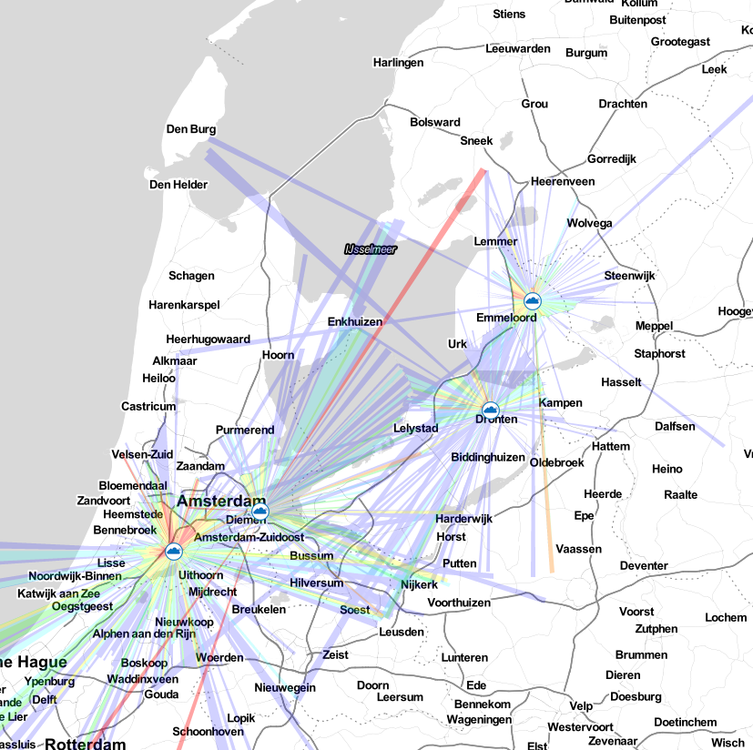
Fig.: LoRaWAN coverage in 2021
In a simulation of radio range coverage, an attempt was made to determine two optimal locations at which professional gateways could be installed on existing radio towers. Coverage would have been ideal with those two locations. Unfortunately, the real implementation failed due to the cooperation of the radio tower operators, because Sigfox offers commercial solutions via the radio towers, which represent direct competition.
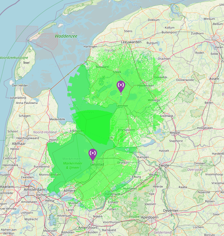
Fig.: Simulation of the wireless coverage of new gateways
In the following winter 2020/2021 a new firmware for the boat monitor was used, with which other spreading factors can also be used. In addition, dynamically variable spreading factors can also be used to make telegram transmission more secure. With SF10 and dynamic spreading factors up to SF12, ranges of up to 45 km were then also achieved, although the antenna of the LoRa boat monitor was only installed inside the boat. From this point on, it was also possible to work without local single-channel gateways. In operation, however, it turned out that the stability of the firmware was not good enough. The firmware still contained a number of errors that had to be eliminated.
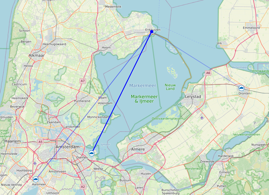
Fig. LoRa connections of the boat monitor with SF10…SF12
Some of the errors were caused by switching from TTN V2 to TTN V3. Both the LoRa boat monitors and all gateways had to be converted to TTN V3 by the end of 2021, as the old network was switched off in 2022. The firmware conversion caused some errors due to functional changes in TTN V3. In particular, the adaptive range control caused us particular difficulties because it constantly sent downlink telegrams to the boat monitor that were misinterpreted and changed the LoRa settings. The whole conversion to TTN V3 created a huge effort and caused further construction sites at Ubidots, since the connection there had also changed. Overall, the transition did not go smoothly. I don't even want to know how the company did with many thousands of devices.
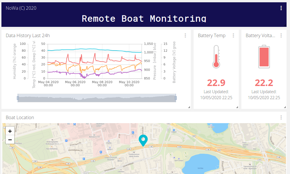
Live tests on a summer weekend showed that the boat monitor is capable of excellent monitoring of charter boats.
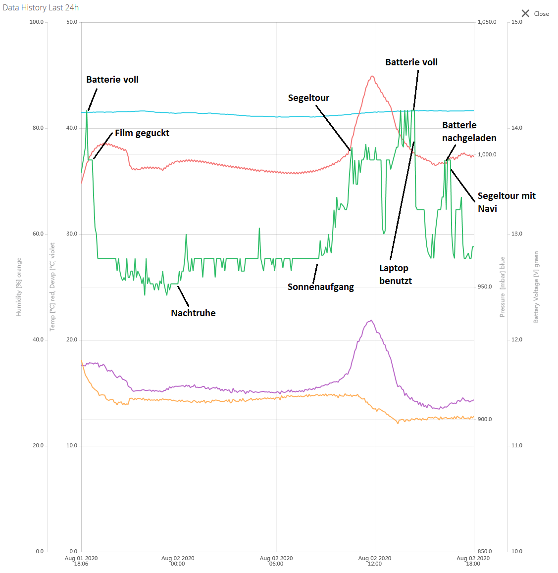
Fig.: Data analysis of a weekend
The largest ranges were achieved with the LoRa boat monitor on Lake Constance near Constance. They were about 60 km.
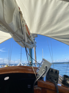
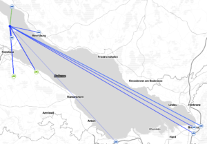
Fig.: Max. range of 60 km at Lake Constance
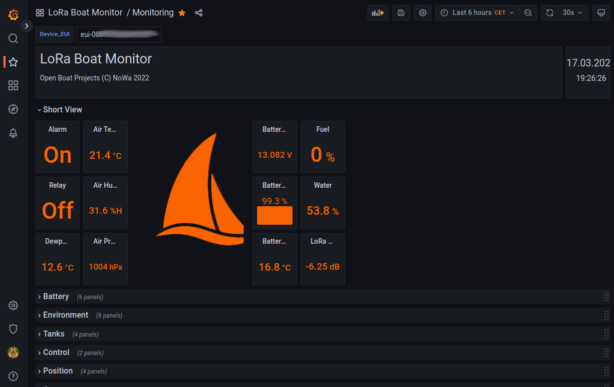
At the end of 2022 for the new winter season, the firmware was completely revised again and the existing errors eliminated. With the new firmware V1.03, a stable state has now been reached again. In addition to a functioning web interface, the measured values can now also be sent as NMEA0183 data. So you can get in SignalK integrate.
Further practical tests are scheduled for the coming 2023 season. In addition, Guntmar is working on a new front end to display the LoRa data without the limitations of Ubidots. the Maritime Data Servers also supports other LoRa devices and microcontroller boards.

Fig.: New frontend
pictures
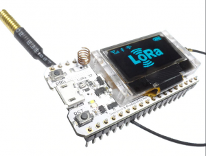
Fig.: LoRa 32 Heltec radio module as a basis
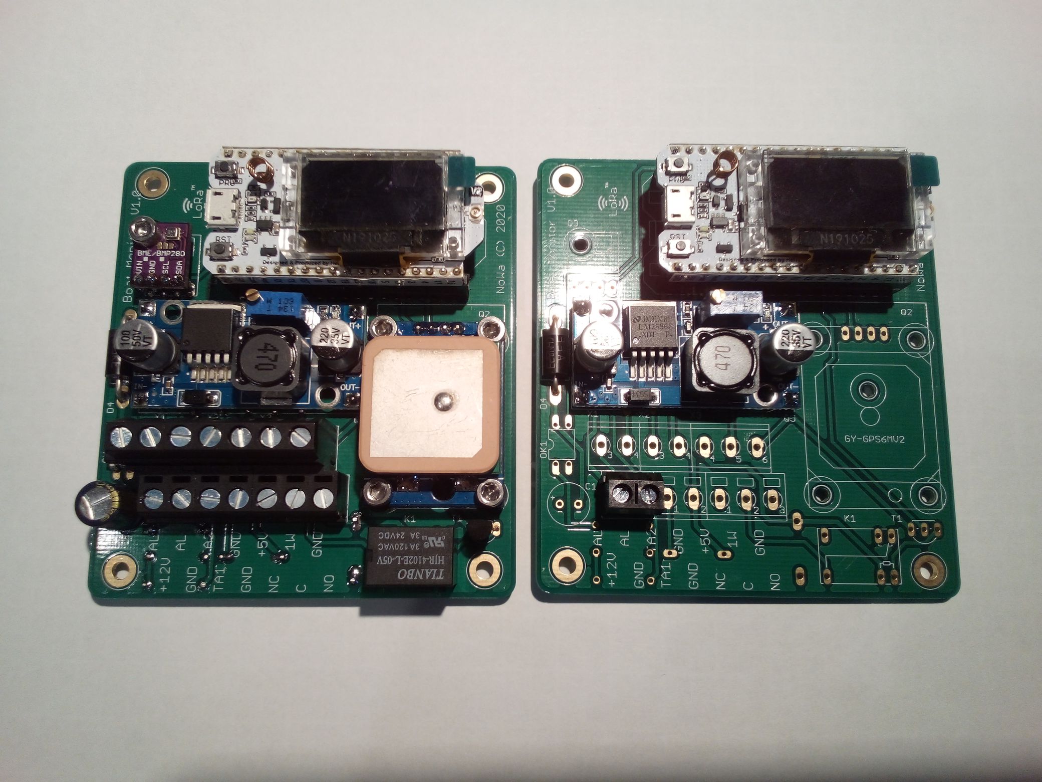
Fig.: Equipped boards (left LoRa boat monitor, right LoRa gateway)

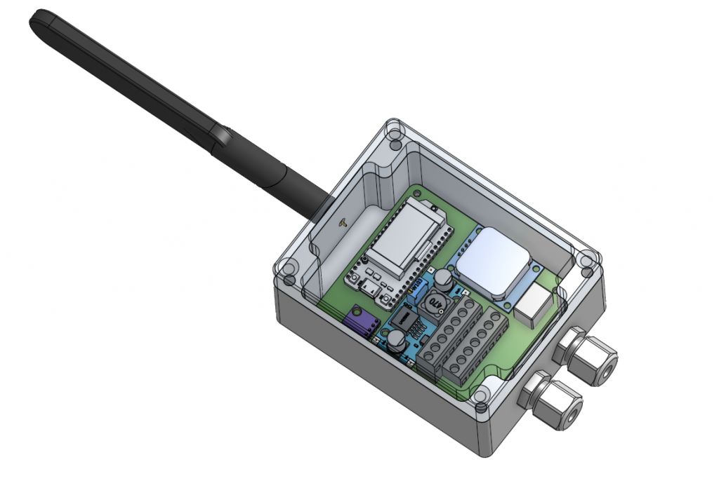
Fig.: LoRa boat monitor
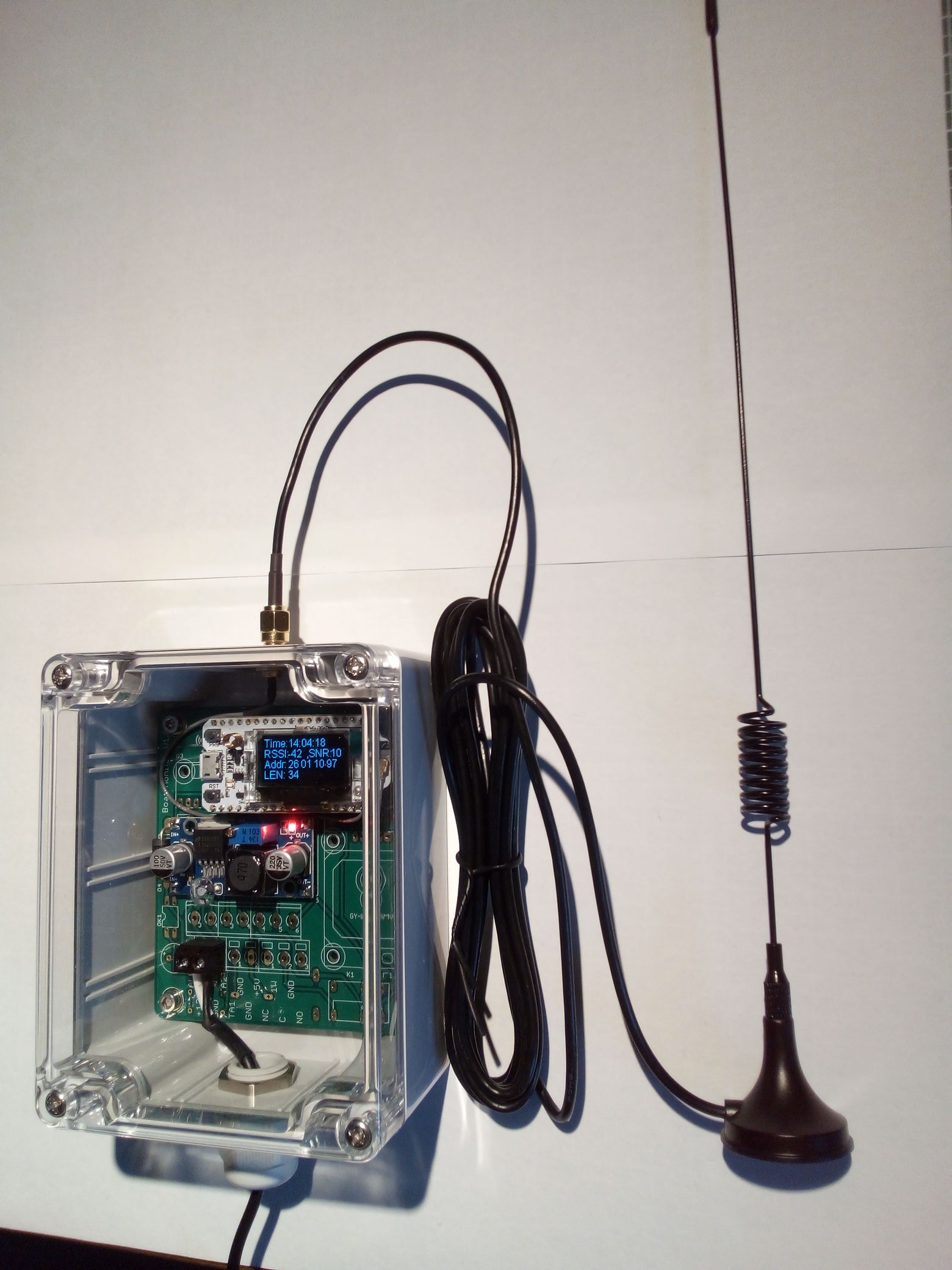
Fig.: Lora gateway