The on-board controller monitors and controls the energy system of a yacht
Development goals
- Increase in operational safety
- Increase in the battery life
- Fast charging of the batteries
Increase in operational safety
The operator is informed about the availability of the battery system at all times by displaying the battery status. An age-related defect in the battery can be diagnosed by a steady decrease in capacity, so a battery change must be planned in good time. A warning is given in plain text against impermissible operating states of the energy system. In this way, measures can be taken before the failure of the electrical power supply and the associated safety risks on board a yacht occur.
Increase in the battery life
The accumulator is charged with a special, temperature-dependent characteristic, which increases the service life. Cost savings are associated with increasing the service life. Yacht accumulators are produced in comparatively small series and are equipped with complex housing designs (leak-proof), which means that their price level is significantly higher than that of automotive accumulators. The capacities used are between 100-1000Ah. Larger battery banks cause considerable installation costs when changing. Disposal less often helps to reduce the burden on the environment.
Fast charge
During charging, the accumulator always receives the optimum current that it can withstand due to its state (state of charge, temperature). If the prime mover is started for the purpose of charging the battery, the charging process should proceed as quickly as possible, since the operation of the prime mover on board a yacht is a considerable noise nuisance. A short charging time reduces the environmental impact.
Functions:
- Control of the automotive alternator according to the special requirements of the electrical energy supply on board yachts
- Monitoring of the energy system and protection against impermissible operating conditions
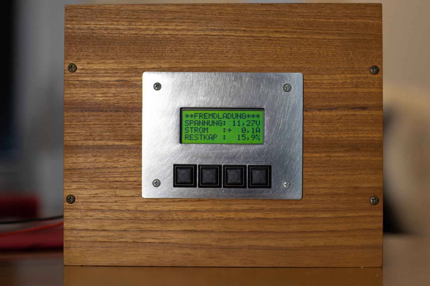
- Display of important system states (charging current, voltage, current and remaining capacity, warning messages)
- Free selection of 3 measured values in the display
- Compact built-in device, 12V / 3W
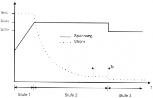
Control of the three-phase generator with optimized characteristic
- Charge with maximum current up to the temperature-dependent gassing voltage UGAS of approx. 14.4V.
- Continue charging with this voltage until the current no longer changes for a period of time (tik).
- The accumulator now receives a temperature-dependent float charge voltage UERH of approx. 13.5 V.
- When the battery temperature reaches 50 ° C, charging is interrupted.
Single line diagram
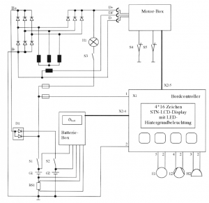
- G1 board battery
- G2 starter battery
- RSI measurement shunt
- SI main switch on-board battery
- S2 main switch starter battery
- S3 ignition switch
- S4 cooling water sensor
- S5 oil pressure sender
- D1 isolating diodes
- H1 charge indicator light
- H2 alarm detector
- E1 consumer
- E2 battery or engine compartment fan
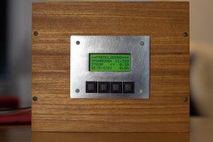
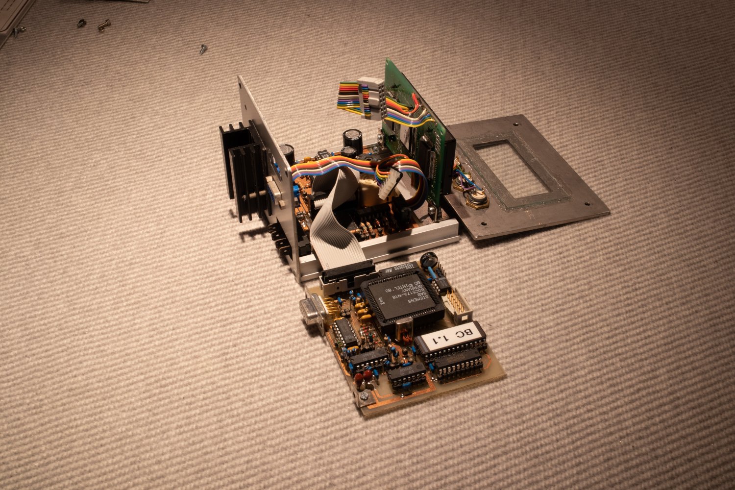
pictures

Contact:
Oliver Bast
oliver (at) basthome.de