First, a few important notes that you should definitely observe.
Often the task with older boats is to connect different sensor networks with each other and to exchange data between the buses such as NMEA0183 and NMEA2000. In addition, you would like to transfer the data via WiFi and see it on a tablet or make it available to a navigation app. For this purpose, there are so-called gateways or WiFi gateways in the commercial sector that solve such tasks. There is now one free OpenSource implementation for the NMEA2000 bus by Timo Lappaleinen that you can use in your own projects. Andreas Koritnik has worked in several Workshops in different Projects shown how to read and feed data on a NMEA2000 data bus. In his workshop, small electronic modules with an ESP32 and CAN line driver are used which have to be soldered in order to obtain a functioning overall circuit. The projects are not complex. But if you have no soldering experience, you hardly dare to undertake such a project.
The Chinese company M5Stack sells small, ready-made and inexpensive electronic modules for the learning area that can be connected to one another by plugging them together and are mechanically compatible with the Lego world. The M5Stack modules are, so to speak, the electronic counterpart to the mechanical building blocks from Lego. So even people without soldering skills can set up individual electronic circuits and make them usable for themselves. You can get a good overview of all the possibilities of the modular system on the M5Stack website.
Universal WiFi NMEA gateway
Andreas Wellenvogel took up Andreas Koritnik's idea and developed it further with these finished modules Software project on GitHub started aiming at a universal WiFi NMEA gateway. The gateway consists of the following basic components:
- Basic components
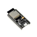
- ESP32 (WiFi-capable, USB)
- CAN bus driver (NMEA2000)
- Power supply
- optional additional modules
- RS485 (NMEA0183)
- RS232 (NMEA0183)
- I2C
- 1Wire
The gateway supports the following protocols:
- NMEA2000
- NMEA1083
- SeaSmart (NMEA2000 over TCP)
- Customer-specific data packets via NMEA0183 with XDR Sentences
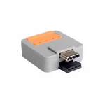
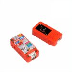
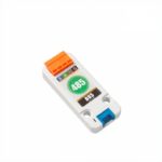
ATOM CANBus Kit
All 3 basic components are e.g. ATOM CANBus Kit from M5Stack contain.

Fig .: ATOM CANBus Kit
The kit consists of two parts. The CAN bus driver as a basic module and the ATOM lite 32 (ESP32 CPU) with the power supply as a small plug-in module. Both parts are put on top of each other and form a unit. This unit is the simplest version of a WiFi NMEA 2000 gateway. With optional additional modules, the basic system can be expanded to include additional interfaces to other bus systems.
Andreas Vogel has developed a firmware that supports a wide variety of hardware combinations of M5Stack modules. Other hardware combinations will certainly be added in the future. The source code of the firmware is designed in such a way that further combinations can be inserted.
Different hardware combinations can be used depending on the application. The combinations differ in terms of the power supply and the additional buses that are available. The additional modules are attached directly to the ATOM light (tail) or connected via a small connection cable (units). The ATOM light is only delivered ex works with hardware diagnostic software and has to be programmed with the respective firmware. You have to be careful to load the correct firmware for the correct hardware combination. All possible hardware combinations are listed in the table. In the last column you can find the associated firmware.
For flashing you can directly use the browser based installer (if your browser supports this). Windows users must install the correct drivers for the serial port.
Hardware combinations
| Type of gateway | Basic module | Additional modules | Supported bus systems | Power supply | Firmware |
| For beginners without soldering experience | |||||
| WiFi Gateway Light
NMEA2000 <> NMEA0183 (WiFi) NMEA2000 <> NMEA0183 (USB) NMEA2000 / NMEA0183 <> SeaSmart (WiFi) |
ATOM CANBus Kit
|
no | NMEA2000 (CAN)
NMEA0183 (USB), NMEA0183 (WiFi) SeaSmart (WiFi) |
5V via USB | Firmware |
| WiFi gateway
NMEA2000 <> NMEA0183 NMEA2000 <> NMEA0183 (WiFi) NMEA2000 / NMEA0183 <> SeaSmart (WiFi) |
ATOM CANBus Kit
|
ATOM Tail485
|
NMEA2000 (CAN)
MEA0183 (RS485) NMEA0183 (WiFi) SeaSmart (WiFi) |
12V via ATOM Tail485 | Firmware |
| WiFi NMEA gateway
NMEA2000 <> NMEA0183 NMEA2000 <> NMEA0183 (WiFi) NMEA2000 <> NMEA0183 (USB) NMEA2000 / NMEA0183 <> SeaSmart (WiFi) |
ATOM CANBus Kit
|
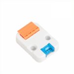
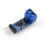
RS485 to TTL converter unit
|
NMEA2000 (CAN)
NMEA0183 (RS485) NMEA0183 (USB) NMEA0183 (WiFi) SeaSmart (WiFi) |
12V via RS485 unit or 5V via USB |
Firmware |
| WiFi gateway
NMEA2000 <> NMEA0183 (WiFi) NMEA2000 <> NMEA0183 (USB) NMEA2000 / NMEA0183 <> SeaSmart (WiFi) |
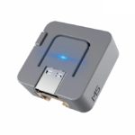
ATOM Light
|
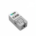
Isolated CAN unit
|
NMEA2000 (CAN)
MEA0183 (USB) NMEA0183 (WiFi) SeaSmart (WiFi) |
5V via USB | Firmware |
| WiFi gateway
NMEA2000 <> NMEA0183 (WiFi) NMEA2000 <> NMEA0183 (USB) NMEA2000 / NMEA0183 <> SeaSmart (WiFi) |
M5STICK C Plus ESP32
|
Isolated CAN unit
|
NMEA2000 (CAN)
MEA0183 (USB) NMEA0183 (WiFi) SeaSmart (WiFi) |
5V via USB | Firmware |
| WiFi NMEA display gateway
NMEA2000 <> NMEA0183 NMEA2000 <> NMEA0183 (WiFi) NMEA2000 <> NMEA0183 (USB) NMEA2000 / NMEA0183 <> SeaSmart (WiFi) NMEA0183 <> SeaTalk (not yet implemented) |
MFD OBP 60 V1.1
|
none necessary, all interfaces included | NMEA2000 (CAN)
NMEA0183 (RS485) NMEA0183 (USB) NMEA0183 (WiFi) SeaSmart (WiFi) SeaTalk I2C 1Wire |
12V over
Electrical system or CAN |
Firmware |
| WiFi NMEA display gateway
NMEA2000 <> NMEA0183 NMEA2000 <> NMEA0183 (WiFi) NMEA2000 <> NMEA0183 (USB) NMEA2000 / NMEA0183 <> SeaSmart (WiFi) |
MFD OBP 60 V2
|
none necessary, all interfaces included | NMEA2000 (CAN)
NMEA0183 (RS485) NMEA0183 (USB) NMEA0183 (WiFi) SeaSmart (WiFi) I2C 1Wire |
12V over
Electrical system or CAN |
Firmware |
| For advanced users with soldering experience | |||||
| WiFi gateway
NMEA2000 <> NMEA0183 (WiFi) NMEA2000 <> NMEA0183 (USB) NMEA2000 / NMEA0183 <> SeaSmart (WiFi) |
ModeMCU32
Adapted to that Board of Homberger. |
CAN driver
|
NMEA2000 (CAN),
NMEA0183 (USB-Serial), MEA0183 (WiFi) SeaSmart (WiFi) |
12V via on-board network or CAN | Firmware |
| Hardware supported in the future | |||||
| WiFi Gateway Light
NMEA0183 NMEA0183 (WiFi) NMEA0183 (USB) NMEA0183 <> SeaSmart (WiFi) |
ATOM RS485 kit
|
no | NMEA0183 (RS485)
NMEA0183 (USB) NMEA0183 (WiFi) SeaSmart (WiFi) |
12V via on-board network | |
| WiFi NMEA gateway
NMEA2000 <> NMEA0183 NMEA2000 <> NMEA0183 (WiFi) NMEA2000 <> NMEA0183 (USB) NMEA2000 / NMEA0183 <> SeaSmart (WiFi) |
ATOM RS485 kit
|
Isolated CAN unit
|
NMEA2000 (CAN)
NMEA0183 (RS485) NMEA0183 (USB) NMEA0183 (WiFi) SeaSmart (WiFi) |
12V via CAN |
|
| WiFi NMEA gateway
NMEA2000 <> NMEA0183 NMEA2000 <> NMEA0183 (WiFi) NMEA2000 <> NMEA0183 (USB) NMEA2000 / NMEA0183 <> SeaSmart (WiFi) |
ATOM CANBus Kit
|
Isolated RS485 unit
|
NMEA2000 (CAN)
NMEA0183 (RS485) NMEA0183 (USB) NMEA0183 (WiFi) SeaSmart (WiFi) |
5V via USB | |
| WiFi NMEA gateway
NMEA2000 <> NMEA0183 NMEA2000 <> NMEA0183 (WiFi) NMEA2000 <> NMEA0183 (USB) NMEA2000 / NMEA0183 <> SeaSmart (WiFi) |
ATOM NMEA2000 kit (Open Boat Projects)
|
Isolated RS485 unit
|
NMEA2000 (CAN)
NMEA0183 (RS485) NMEA0183 (USB) NMEA0183 (WiFi) SeaSmart (WiFi) |
12V via CAN | |
| WiFi NMEA display gateway
NMEA2000 <> NMEA0183 (WiFi) NMEA2000 <> NMEA0183 (USB) NMEA2000 / NMEA0183 <> SeaSmart (WiFi) |
M5STICK Core2
|
Isolated CAN bus unit
|
NMEA2000 (CAN)
NMEA0183 (RS485) NMEA0183 (USB) NMEA0183 (WiFi) SeaSmart (WiFi) |
5V via USB | |
| WiFi NMEA display
NMEA0183 (WiFi) SeaSmart (WiFi) |
Lilygo T-Watch 2020
|
none necessary | NMEA0183 (WiFi)
SeaSmart (WiFi) |
3.7V battery |


Program firmware via USB
Please note the following when programming the firmware for the ESP32. When programming for the first time, you need special firmware that creates different partitions in the flash memory. In addition to the actual firmware in the partition app0 will still have partitions for app1 (Backup copy of the firmware), nvs (Configuration data) and otadata (Over the Air Flash function) required. The following table shows the arrangement of the respective partitions in the 4 MB flash memory.
| Surname | Type | Subtype | Offset | Size |
| nvs | data | nvs | 0x9000 | 0x5000 |
| otadata | data | ota | 0xe000 | 0x2000 |
| app0 | app | ota_0 | 0x10000 | 0x1f0000 |
| app1 | app | ota_1 | 0x200000 | 0x1f0000 |
Table: Partition table of the firmware
To simplify the flash process, all required partitions were combined in a binary file. The file is named
xxxxx-xxxx-all.binmarked.
The most simple method for flashing is to use the browser based installer (if your browser supports this). Windows users must install the correct drivers for the serial port.
The firmware can be used with the esptool Load from Espressif. The tool consists of a series of Python scripts that execute the flash process. Linux users can use the esptool very easily via the PIP package manager
sudo pip install esptoolto install. In order to be able to execute the scripts, however, you need a Python interpreter which you have to install. The Python interpreter can be found here under for common operating systems such as Linux, Windows and Mac download and install.
Current Linux operating systems already have USB serial drivers. You don't have to do anything else. Under Windows you have to install the USB serial driver for Windows before programming. Otherwise you will not be able to establish a USB connection to the ATOM device. The driver can be found at FTDI:
Note: The drivers offered on the M5 site do not seem to work (see USB Drive Problems)
After installing the drivers in the Windows device manager, make sure that a new USB device is added under Serial Devices when you connect the ATOM device to the PC. Make a note of the corresponding COM interface. We need them for the later flash process.
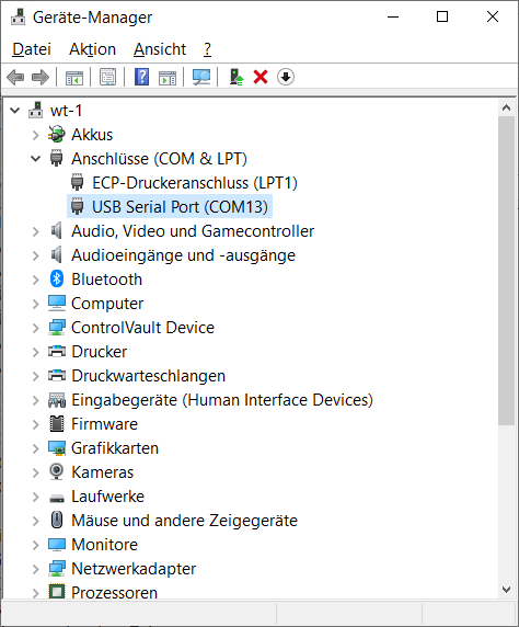
Fig.: Windows device manager
Linux users
Use the firmware stored in the table above for flashing. The required flash command for the WiFi gateway light (m5stack-atom) would be the following:
esptool.py --port XXXX --chip esp32 write_flash 0x1000 m5stack-atom-XXXXXXXX-all.bin
XXXX after –port must be replaced by the corresponding serial interface designation. For the meaning of the board names see hardware . For more information, see the code in platformio.ini and in the hardware definitions in GwHardware.h .
Windows users
With esptool.exe You will find a ready-made executable file in the project folder under tools, which saves you an additional installation of the Python interpreter, as the interpreter is already integrated in esptool.exe. Simply create an empty directory on your computer, download the esptool.exe into this directory and also download the firmware (xxx-all.bin) from the table above. Open a command prompt and change to the directory where you downloaded the esptool.exe and the firmware binary file. With the command
esptool.exe --port COM13 write_flash 0x1000 xxxxx-xxxx-all.bin
flash the firmware via the serial USB interface COM13. It may well be that you still have to adjust the USB interface on your PC.
On the Project page there is also an explanation of how you can apply the firmware (under Windows) with a graphical tool without having to use the command line.
Firmware update via web UI
To update the firmware of a device later, you can use the web UI (Update tab). Do not use the initial firmware for this. For updates via the web UI, there are special firmware files that only contain the partition with the firmware. This means that your configuration is retained even after the flash process. In principle you could also update a device with the initial flash firmware (and a xxx-all.bin) firmware, but this would erase your entire configuration. So for normal operation just download a xxx-update.bin from the Release Page and use the user interface to install it.
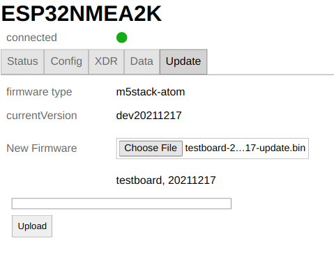
Fig .: Update via web UI
When you select a file for the update, the user interface checks whether it is a valid firmware file and rejects invalid ones. To actually run the update, click the button UploadYou will receive a progress bar and a notification about the update result. After a successful firmware update, please reload the page in your browser after the "connected" status turns green. This is the only way to ensure that potential extensions that were not previously available in the web UI will work in the new version.
Installation
After successfully flashing and starting the firmware, a WiFi access point is created. Connect to the WiFi network ESP32NMEA2K and the password esp32nmea2k. Then use the address in a web browser ESP32NMEA2k.local or the IP address 192.168.15.1. You get a small user interface to monitor the status and make settings.
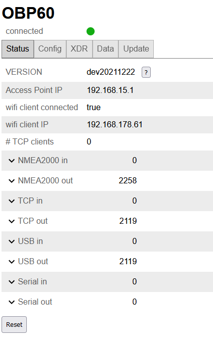
Fig. Status page
If you want to connect to a different WiFi network, simply enter the access data in the WiFi client tab and activate the WiFi client. For all potential inputs and outputs (NMEA2000, USB, TCP, RS485) you can set the configuration including NMEA0183 filtering. To save your changes, you will be asked for a Admin password asked. The initial password is esp32admin. You can change this password on the config / system tab or even disable it completely. Be careful not to lose the password. You can only restore a lost password by performing a factory reset of the device (press the LED button for a long time until it lights up blue-> red-> green). To help you to recover lost passwords, the password of the WLAN access point and the admin password are output to the USB port when the device is started. You can call up these passwords by connecting a terminal program.
safety instructions
You should only connect the device to trusted Wi-Fi networks. There is very limited protection against network sniffing or denial-of-service attacks. Never connect the device directly to the internet without using a firewall, such as a Wi-Fi or LTE router. Be especially careful when connecting to open port networks. Whenever changes are made, you will be asked for the admin password – and this is always sent encrypted. However, if you change the Wi-Fi access point password or the Wi-Fi client password, it will be sent in clear text. If you enable "Remember me" for the admin password, it will be stored in plain text in your browser. ForgetPasswordto remove it from there.
Connection to the NMEA2000 bus
Connector system
For the NMEA2000 bus, there are standardized, waterproof and shielded 5-pin plug connections in M12 format. Depending on the design, they can be made entirely of plastic or partially of metal. In addition to the data lines CAN-H and CAN-L, there are two lines for the power supply such as GND (V-) and + 12V (V +) as well as a connection for the shield. Cable connections for sensors are usually designed as plugs (male) and have an external thread. Bushings, on the other hand, always have a union nut with an internal thread.
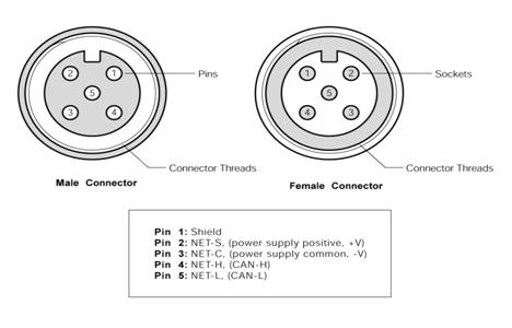
Fig. Top view of the contact side
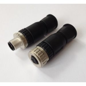
Fig.NMEA2000 connector for self-assembly (Busse yacht shop)
If you want to buy much cheaper industrial connectors outside of the yacht accessories trade, make sure to buy 5-pin connectors with A-coding. The index notch is then located between pin 1 and 2. There are other codes where the index notch is in a different position.
SeaTalk NG, Simnet and Philippi P-Bus are similar bus systems that are based on the CAN bus as a physical layer. However, they differ from NMEA2000 in some specifications and are not 100% compatible. In addition, each manufacturer uses its own connectors that are not compatible with each other with NMEA2000. With the appropriate converter cables, however, data can be exchanged between these networks. Basically, a mixture of different bus technologies should be avoided.
Power supply from the bus
NMEA2000 devices with low power consumption such as sensors can also be supplied with power from the bus system. No additional supply cables are necessary. The 12 V supply voltage is fed into the NMEA2000 bus either via a feed cable or a plotter with bus feed. However, it must be ensured that only a limited power of up to 35W may be drawn from the NMEA2000 bus. The NMEA2000 devices are marked with load values that indicate the current drawn from the bus. The load is specified as a multiple of 50 mA. A device with Load 3 would therefore need 150 mA at 12V and consume 1.8 W of power. The 12 V supply voltage should ideally be fed into the bus in the middle, as this minimizes line losses due to line resistance.
cable
Only high-quality, waterproof and shielded industrial cables should be used as bus cables, such as Lapp bus cable UNITRONIC 2 x 2 x 0.34 mm².
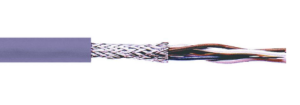
Fig.CAN bus cable
Two single wires are twisted in pairs and also surrounded by an outer braided shield. One twisted wire pair is used for CAN-H and CAN-L and the other wire pair for GND and 12V. The braided shield is connected to GND on one side. This will give you the best results and a safe and durable installation. Cables thinner than 0.34 mm² should not be used if the supply is to come from the bus. The total length of the bus cable should not exceed 40 m.
Termination
The physical layer of the NMEA2000 bus is based on the CAN bus With differential signal transmission. Two signals with opposite polarity are transmitted from the transmitter and a single signal is generated in the receiver by subtracting the two signals. Disturbances that affect both signal lines in the same way are eliminated by the subtraction. This enables a robust signal transmission that is not susceptible to interference.
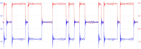
Fig.Differential data transmission (red CAN-H, blue CAN-L)
A CAN bus uses terminating resistors of 120 Ohm between the lines CAN-H and CAN-L at both ends of the bus system. The two terminating resistors correspond to the line resistance of 120 ohms and prevent signal reflections at the line ends at high data transfer rates of 1 Mbit / s. The CAN bus consists of a long bus line with short stub lines less than 1.5 m. A star structure of the bus system is not permitted. The two terminating resistors may only be installed at the end of the bus and may not be in between.
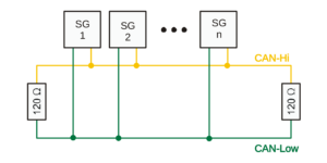
Fig.CAN bus structure (without power supply)
Some devices have built-in terminating resistors that can be switched on or off using the appropriate switches. Before installing new devices, make sure that integrated terminating resistors are used and how they are configured. Incorrectly terminated buses can cause transmission problems that are difficult to find.
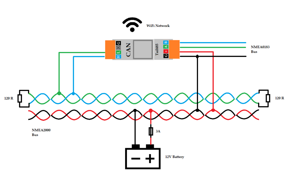
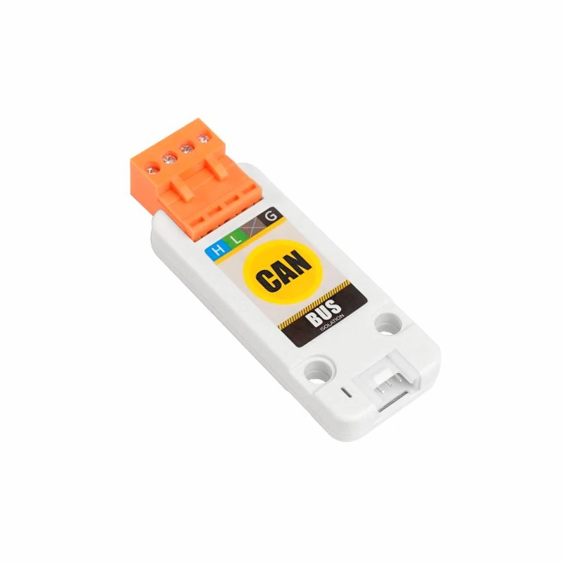
Fig.CAN bus connection with supply from the bus (M5Stack Atom with Tail485)
The connection to the NMEA2000 bus is made via the orange connector of the ESP32 CAN kit and the 12V power supply via the Tail485.
Valuable connection options are in the Repository at Github described.
Connection to the NMEA0183 bus
A connection to the NMEA0183 bus is possible via the orange connector of a Tails485 or an RS485 unit, depending on the hardware used. With the RS485 modules from M5Stack specified in the table above, the bus can be accessed either read or write. This can be selected in the configuration of the web UI. The parameters (baud rate, filter) for the interface can also be set there. The baud rate is set to 4800 Bd by default and thus supports most devices. Depending on the device, a higher baud rate, such as for an AIS receiver, can be set, provided it supports these baud rates. It should be noted, however, that the sensitivity to interference increases at higher baud rates and the permissible bus length is shorter. In terms of cabling, the NMEA0183 bus is less critical than the NMEA2000 bus. No special cables are required. Shielded cables are recommended to avoid interference. The cable cross-section should be 0.34 mm².
Integrate your own hardware
The source code of the firmware is designed so that further hardware combinations or your own hardware can be added. You can easily adjust the PIN assignment for your own hardware or add your own code. In the project there is an example about folders lib / exampletask included, there is also one description Further examples can be found in “forks” of the project – e.g. free-x or norbert-walter.
known problems
NMEA2000 critical: There is probably a problem with the implementation of the CAN protocol stack in the ESP32 when communication is started on the bus. If the start-start sequence is not answered by the communication partner, the CAN bus of the requesting ESP32 goes into an undefined state and sends garbage data at full data rate until the start-start sequence is answered by any communication partner in the bus. If you have connected both ESP32 to the CAN bus and then reset both or one of the ESP32s, the connection works again. It looks like you can only use the start-start sequence once after a reset. After that it no longer works. However, if there are other communication partners in the CAN bus who do not use an ESP32 and can still respond correctly to the initial sequence, everything is ok. The problem only occurs when two or more ESP32s want to communicate with each other.
The problem has now been solved by corrections in an open source library.
NMEA2000 critical: If no terminating resistors or the correct terminating resistors are used on the CAN bus, this can lead to malfunctions on the bus. Either data packets are lost or the CAN bus hangs completely or does not start at all. This occurs in particular when unshielded and non-twisted cables are used or when the data lines CAN-H and CAN-L are touched by hand or these lines come into high-resistance connection with GND or + 12V. The CAN bus can only be revived if the voltage is completely switched off and all systems are then restarted. Such problems do not occur if the CAN bus is correctly terminated and suitable cables and plug connections are used.