First of all, a few important notes that you should definitely pay attention to.
While searching the Internet for a battery monitor for DC voltages, I came across the PZME-017. The Peacefair company is known for various inexpensive battery monitors with LCD displays such as the PZEM-015.
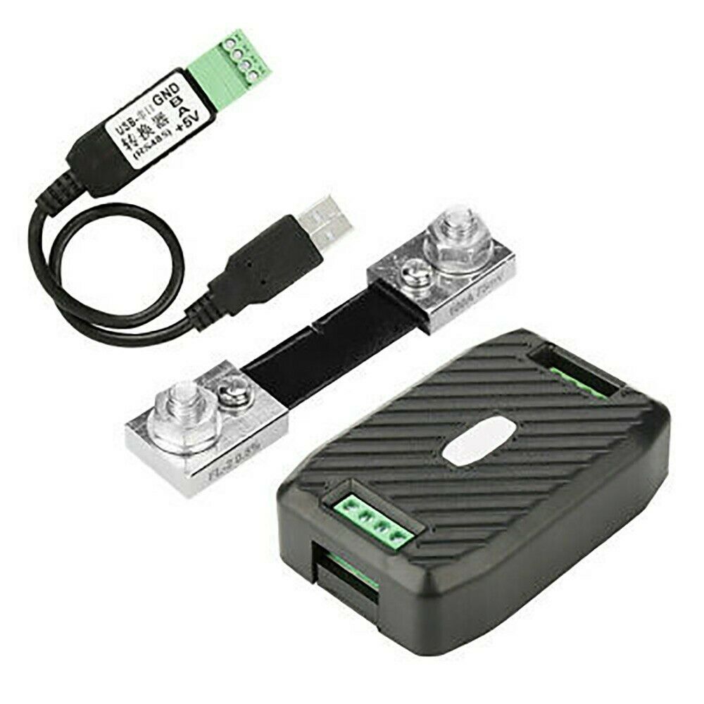
Fig: PZEM-017 (100A version, with shunt and USB-RS485 adapter)
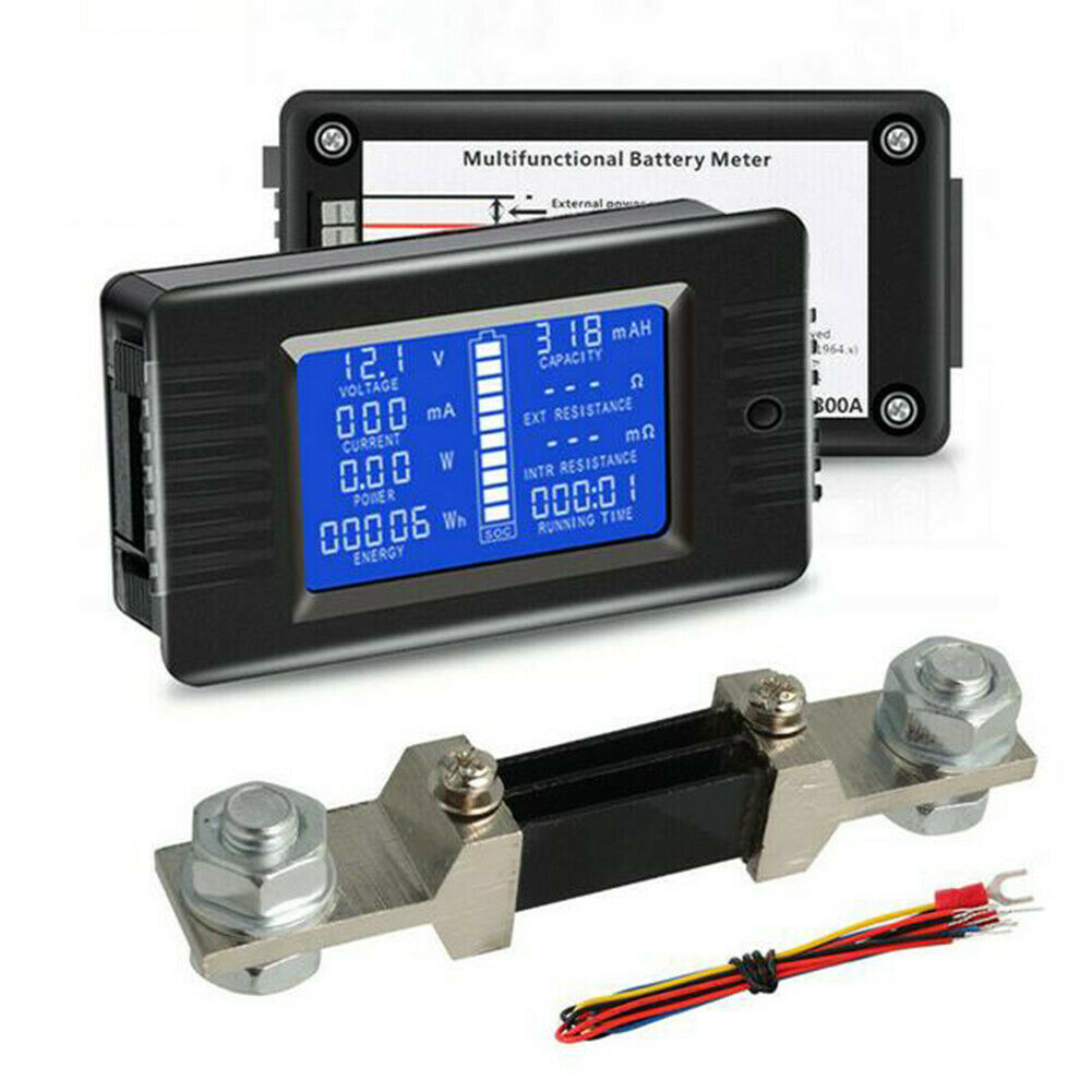
Fig: PZEM-015 (300A version as a pure display variant)
The PZEM-017 has the following features:
- Voltage measurement 0… 300V DC
- Current measurement: 10A, 50A, 100A, 200A, 300A (from 50A via external shunt)
- Display of the current power in watts
- Energy display in kWh for the current day, previous day and total consumption display
- Modbus RTU-Interface (RS485, 9600Bd, 8N2, binary data transmission)
- Supported Modbus commands:
- 0x03 Read memory register
- 0x04 Read input register
- 0x06 Write single register
- 0x41 calibration
- 0x42 Reset energy measurement
- 7 devices can be used on the Modbus via adjustable ID 1… 7, ID 0 broadcast
- USB-RS485 adapter (CH341)
In contrast to the PZEM-015, the PZEM-017 has no display and transmits the measurement data via the Modbus. The Modbus protocol is open and there are some implementations with an arduino. The website is an example here Solarduino called. There, however, a TTL-RS485 adapter is used to connect to the Arduino. In the area of home automation there are implementations with a Wemos D1 mini (ESP8266) with Tasmota firmware and a data connection via WiFi. However, it cannot be used well as a battery monitor on a boat, as you still need an external power supply of 5V for the Wemos D1 mini.
The Tasmota firmware already has all the important interfaces that you need to be able to build a boat battery monitor:
- Supports all PZEM modules with Modbus interface via TTL signals with unsoldered RS485 chip (U5)
- Supports temperature 1-wire modules such as the DS18B20
- Web configuration
- Display of the measurement data on the website
After some reengineering of the electronics I was able to modify the circuit so that it does not need an additional 5V supply and only needs a few components such as:
- Wemos D1 mini with Tasmota firmware
- 1k resistor
- 4K7 resistor
- 7 connection cables
- DS18B20 temperature sensor
and a stand-alone boat battery monitor has been created that can:
- Input voltage 10… 38V
- Voltage measurement accuracy: 0.01V
- Current measurement: 10A, 50A, 100A, 200A, 300A (from 50A via external shunt)
- Current measurement accuracy: 50mA
- Display of the current power in watts
- Energy display in kWh for the current day, previous day and total consumption display (not power off resistant when completely switched off, details look here)
- Resettable energy meters
- Configuration and display of the measurement data via the website
- Temperature measurement: 1… 3 DS18B20 for battery, charger and inverter (operated in parallel on the 1-Wire bus)
- Own consumption: 16mA (without WiFi activity), 60mA (with WiFi data traffic, if connected)
- Reduced power consumption of only 1.0mA when the Wemos D1 mini is switched off (look here)
Circuit modification
Unsolder IC U5 (MAX485)
The IC U5 is not required because we do not use the Modbus and connect the serial TTL data signals (3.3V) directly to the Wemos D1 mini. The easiest way to unsolder it is with a hot air desoldering station. If you don't have this, you can heat up each pin of the IC individually with the soldering iron and carefully bend it up with a needle. But you have to make sure that the pin is not heated for too long, otherwise the conductor track underneath will become detached from the circuit board. This must be avoided at all costs, as we still need the pads to solder the cables. It is also important to note how U5 was soldered in, as the cables are soldered according to the pin numbers according to Table 1.
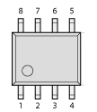
Fig: Pin numbers

Fig: Position of U5 (unmodified board)
Solder in 1k resistor
The 1k resistor has to be soldered parallel to R15. R15 is the series resistor for controlling the optocoupler U2 (CT817C Receiving side). With the resistor soldered in parallel, R15 is reduced to 320 Ohm, so that the LED of the optocoupler can be controlled from the Wemos D1 mini with a 3.3V TTL signal.
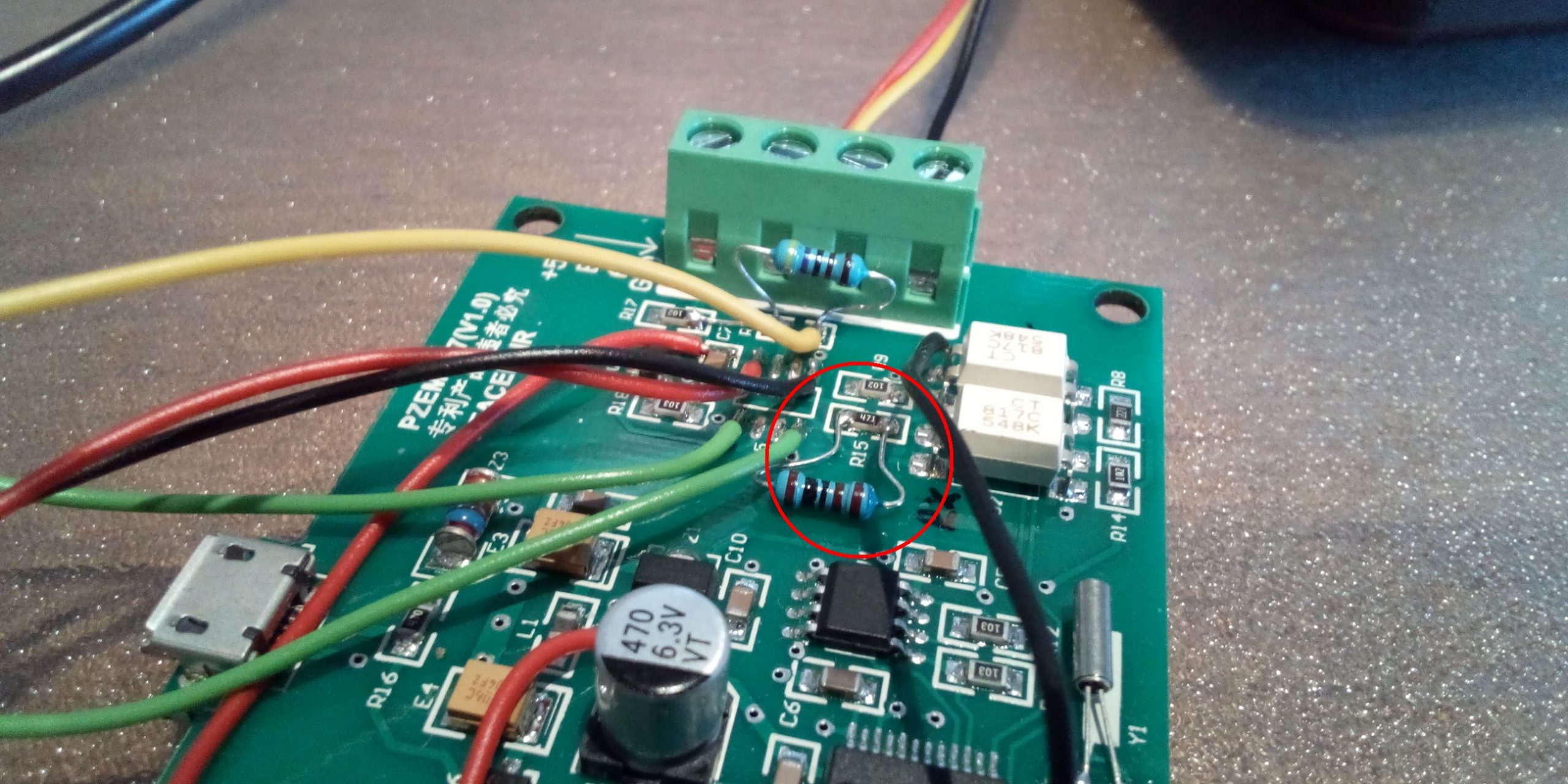
Fig: 1k resistor
Solder the 4K7 resistor and bridge
The 4k7 resistor serves as the Pull-up resistor for the 1Wire bus. It is soldered to the pads of the missing resistor R19. In addition, a small bridge from R19 to R17 is soldered as can be seen in the picture. This connects the resistor to 3.3V.
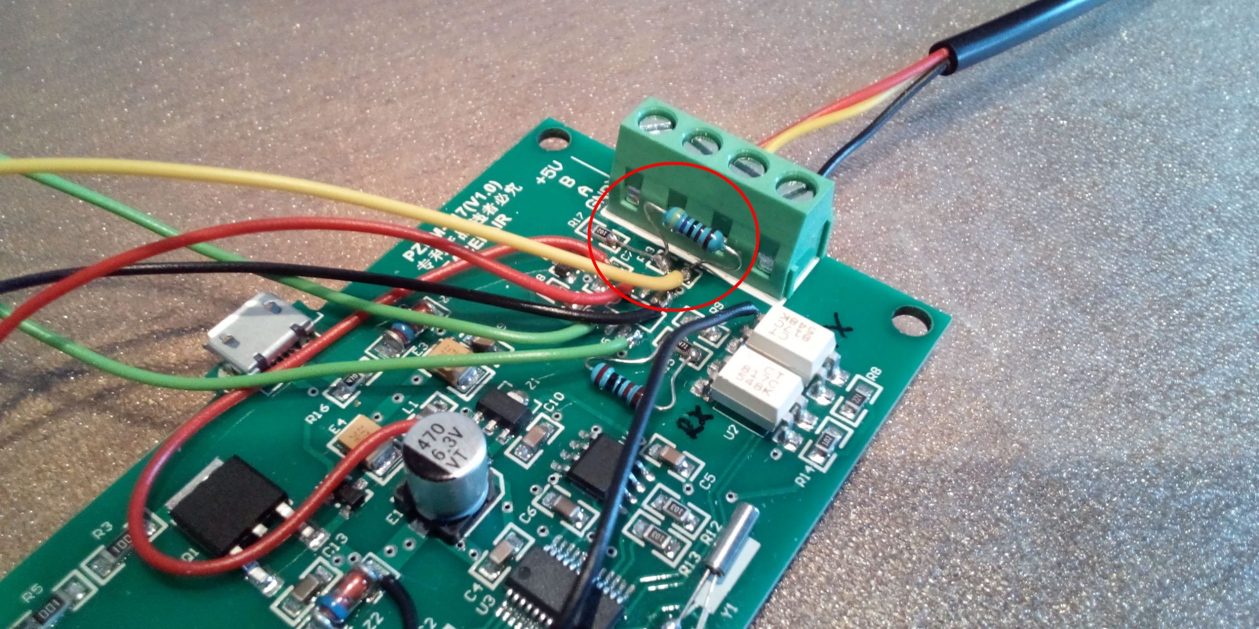
Fig: 4k7 resistor with bridge
Solder the 3.3V supply voltage to the Modbus output circuit
Since the Modbus output circuit is operated electrically isolated from the measuring circuit via the optocoupler, an external supply voltage of 5V is required in the original circuit. This is fed in via the Modbus connections. In our case, however, we do not need electrical insulation, as we transmit the data via WiFi and operate the rest of the circuit with the same 3.3V supply voltage as the measuring circuit. For the feed we need a black cable from Z2 to U1 pin 3 and a red cable from plus E1 to C7.
The optocouplers actually no longer make sense. We still need them because the signals from the microcontroller U3 are inverted and we cannot use them directly.
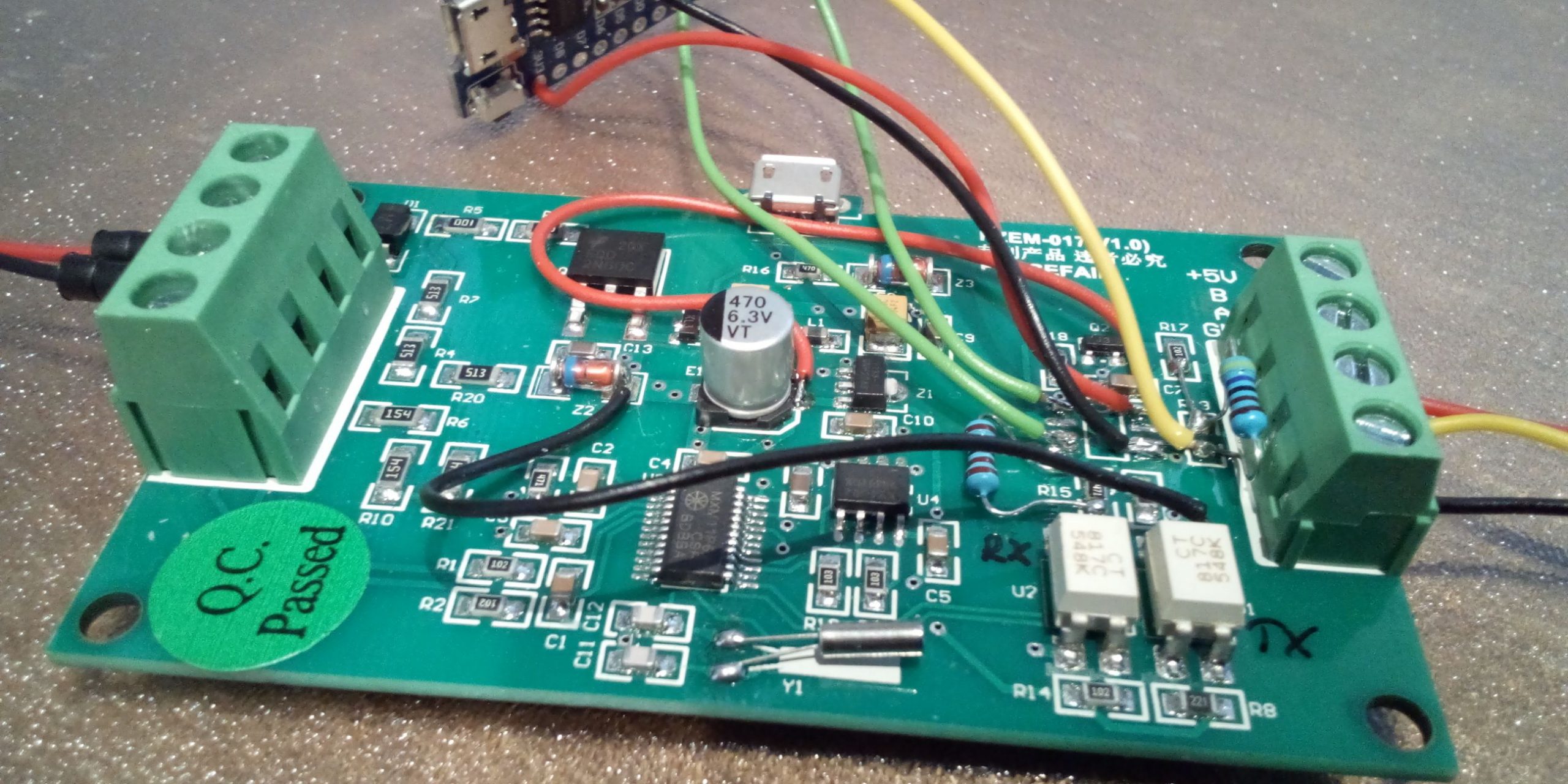
Fig: Supply lines
Solder in the Wemos D1 mini
The connections of the Wemos D1 mini are soldered to the free pads of U5 as follows:
| Cable color | From Wemos D1 mini | To | meaning |
| red | 3V3 | U5 pin 8 | 3.3V supply |
| black | G | U5 pin 5 | Dimensions |
| green | TX (GPIO 1) | U5 pin 1 | Receive Modbus |
| green | RX (GPIO 3) | U5 pin 4 | Send Mosbus |
| yellow | D1 (GPIO 5) | R19 lower pad | 1-Wire data signal |
Tab. 1: Cable assignments

Fig: Pin assignment Wemos D1 mini
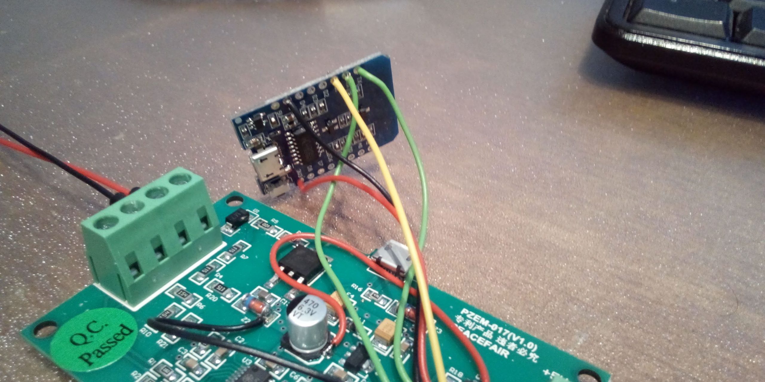
Fig: Cable on the Wemos D1 mini
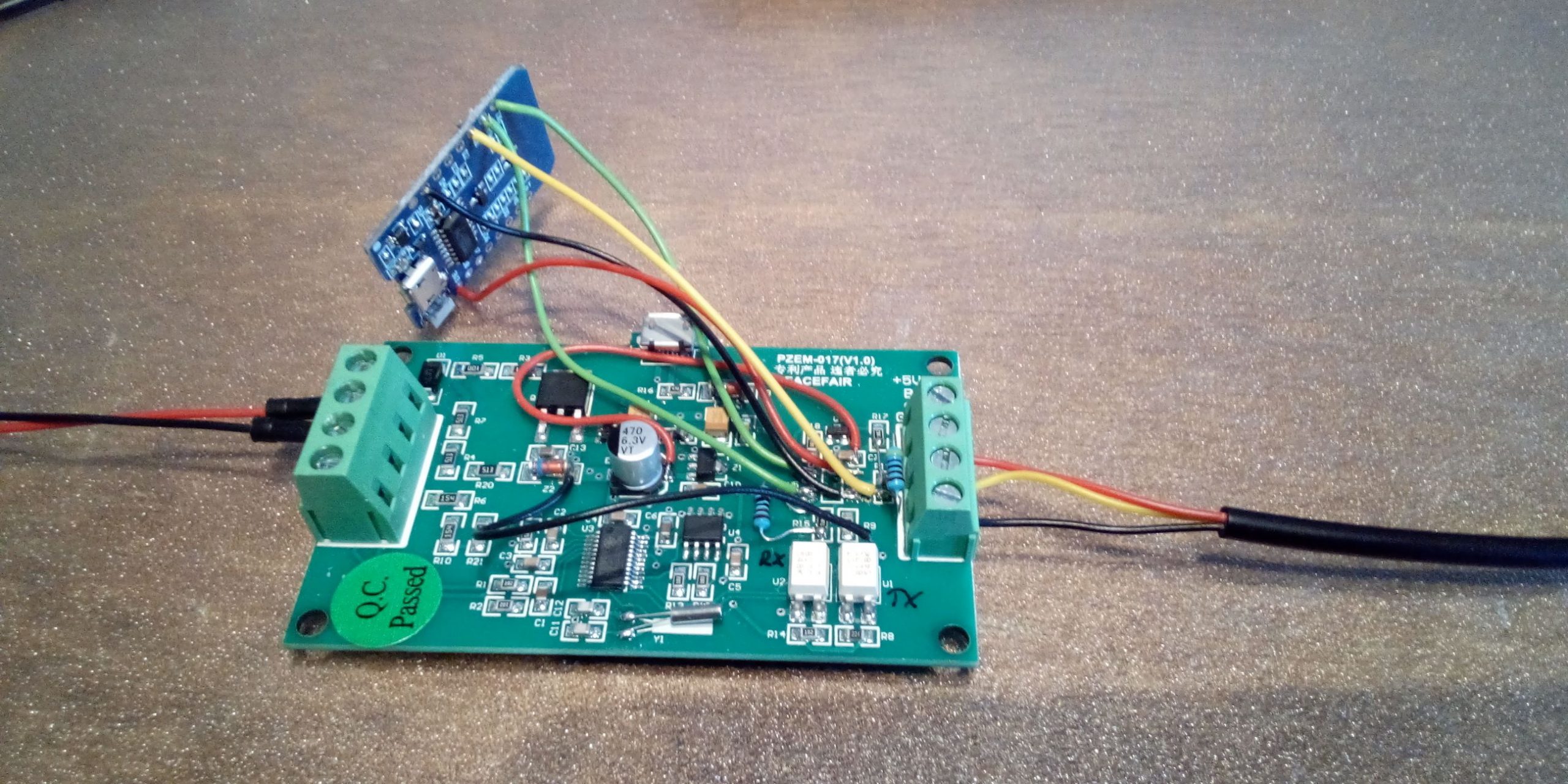
Fig: Assignment of the cables to U5
Flash Tasmota firmware
Before the Tsmota firmware is flashed, the following must be observed:
Note! In our modified circuit, the Wemos D1 mini is not operated with the 5V supply, but with 3.3V directly from the measuring circuit. If the Wemos D1 mini is supplied with 5V via the USB connection, the battery monitor must be disconnected from the 12V supply and from the shunt. Otherwise there will be a double feed and the Wemos D1 mini or the PC could be damaged. So all 4 cables must always be disconnected from the measurement connections when working with the USB cable.
The current version of the Tasmota firmware can be downloaded here: http://ota.tasmota.com/tasmota/release/ The firmware is available in different language versions. The tasmota.bin file would be a good choice for English-language firmware. If you want to know more about Tasmota, you can visit this website: https://www.tasmota.info There you will find detailed information about supported hardware and flashing.
The easiest way to flash the firmware is with the software Tasmotizer which are available for different operating systems. It works best with the Windows variant.
When flashing via USB cable, don't forget to check the "Self-resetting device" box. This will automatically put the Wemos D1 mini into programming mode and reset it after flashing.
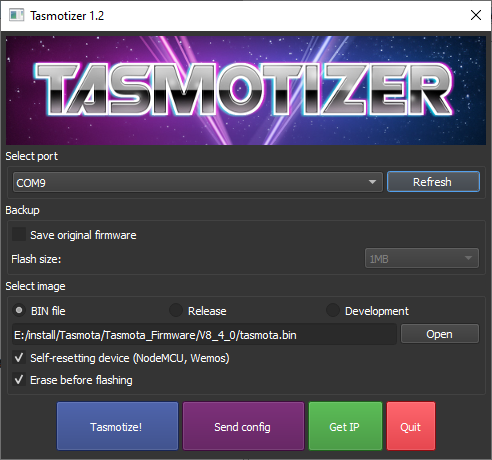
Fig: Tasmotizer settings
Tasmota configuration
The Tasmota firmware is universal and supports a variety of devices. With the configuration, the firmware is adapted to the specific hardware. After flashing, the Wemos D1 mini starts with its own access point, which can be reached under the SSID tasmota_xxxxxx. A password for logging into the WiFi network is not required. The start page can be opened with a web browser under the IP address 192.168.4.1. The respective settings are made under Configuration as shown in the following images.
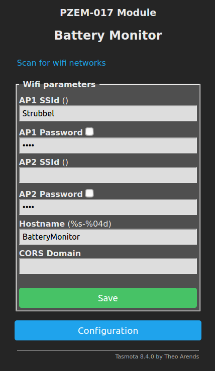
Fig: Configure WiFi: Enter SSID, password and host name
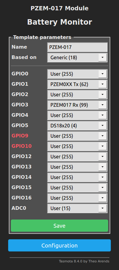
Fig: Configure tamplate: Select Based on Generic (18), assign the name PZEM-017 and assign GPIOs
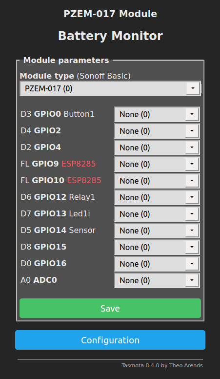
Fig: Configure Module: Select module type PZEM-017 (0)
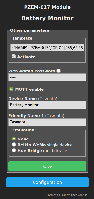
Fig: Configure Other: Assign Device Name Battery Monitor
This completes the configuration and we can see the measured values on the start page of the battery monitor.
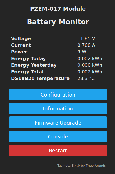
Fig: Battery monitor home page
Safe installation in the housing
The Wemos D1 mini can be accommodated in the same housing as the battery monitor. I packed the Wemos D1 mini in a small zip bag. This means that no short circuits can occur with the rest of the circuit and everything is securely packaged. You could of course do the isolation with tape. With the zip bag, however, it is more convenient because you can remove the Wemos Di mini for later software changes.
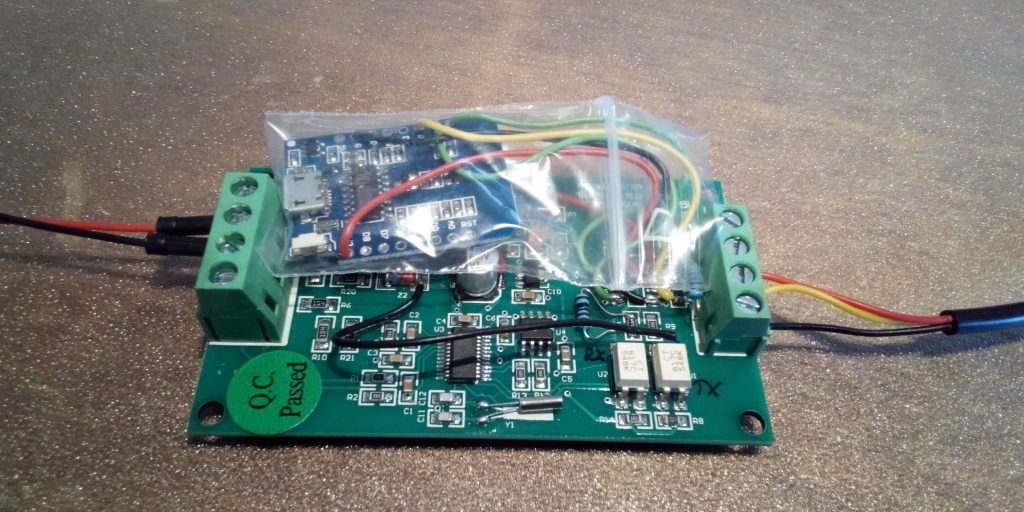
Fig: Isolation of the Wemos D1 mini in a zip bag
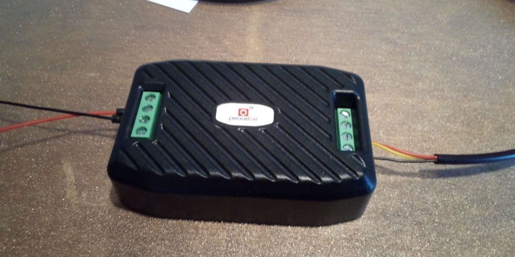
Fig: Closed housing
Connection of the temperature sensor
The DS18B20 temperature sensor can be connected to the connections of the RS485 bus as follows:
| Connection RS485 port | New function | DS18B20 |
| 5V | 3.3V | not used |
| B. | 3.3V | red |
| A. | 1-Wire | yellow |
| GND | GND | black |
Tab: Terminal assignment temperature sensor DS18B20
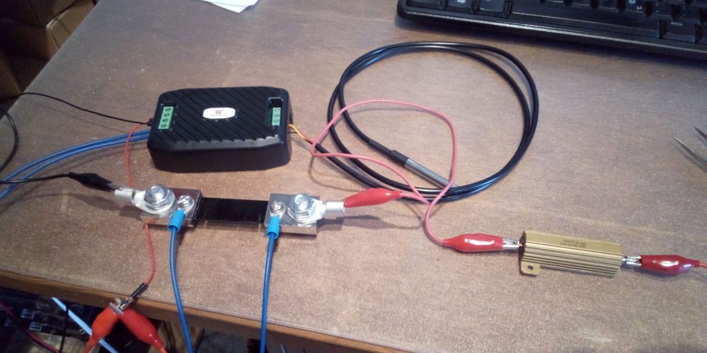
Fig: Test circuit with shunt, load resistor and temperature sensor equivalent to the circuit diagram on the back of the battery monitor
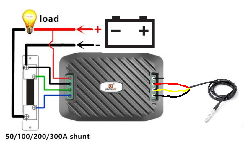
Fig: circuit
Further information
Separate micro USB port
The separate micro USB port on the side of the battery monitor is used for power supply if the battery voltage should drop below 7V. A separate USB cable can then be used to supply an external power supply. As noted in the documentation, this is very dangerous if the battery voltage is greater than 7V. Then the feeding devices can be destroyed via the feed from a PC or a power bank, because the higher voltage is then applied to the feeding devices with the maximum current of the battery. It is therefore not advisable to use this micro USB port. It's just too dangerous.
1-wire port
Up to 3 temperature sensors can be connected in parallel to the 1-Wire port. The sensors can be used, for example, to measure the temperature of the battery, the charger, the solar regulator or the inverter. Any other application would also be conceivable. The Tasmota firmware will automatically detect the additional temperature sensors and display the temperature values below the values from the battery monitor. The assignment of the sensors to the IDs must be found out by testing the sensors.
Power supply
If the battery voltage is less than 10V, the WemosD1 mini will no longer function properly. The Wemos D1 mini gets stuck, especially when switching on with voltages below 10V. Overvoltages above 40V are possible, but should not be present for too long as the power supply heats up significantly.
Current measurement
The current measurement with the PZEM-017 shows an offset of 0.05A for a 100A shunt and thus falsifies the counting of the amount of energy. Only positive measuring currents can be processed. Negative currents through chargers are permitted, but are not taken into account in the energy measurement.
Subsequent change of the shunt value
When the PZEM-017 is delivered, the correct shunt value is entered in the firmware. If you want to use other shunt values, you can reprogram this using the Modbus commands before converting the circuit. It should be noted, however, that the shunts must be designed for 75mV and only the shunt values for currents 50A, 100A 200A and 300A are supported. Switching to other shunt values is done exclusively by software. Internally, only another conversion of the voltage measured at the shunt is carried out. The measurement accuracy is therefore dependent on the shunt used. The measured values for shunts are correspondingly more accurate for smaller currents and less accurate for higher currents.
Setting the shunt value:
01 06 00 03 00 00 79 CA 100A
01 06 00 03 00 01 B8 0A 50A
01 06 00 03 00 02 F8 0B 200A
01 06 00 03 00 03 39 CB 300A
01 06 00 03 00 04 78 09 10A (internal shunt)
01 - ID
06 - write parameters
00 03 - register no.
00 00 - Shunt value (00 00 - 100A)
79 CA checksum
Answer:
01 06 00 03 00 00 79 CA 100A
01 06 00 03 00 01 B8 0A 50A
01 06 00 03 00 02 F8 0B 200A
01 06 00 03 00 03 39 CB 300A
01 06 00 03 00 04 78 09 10A (internal shunt)
01 - ID
06 - write parameters
00 03 - register no.
00 00 - Shunt value (00 00 - 100A)
79 CA checksum
Energy measurement
The energy measurement is a measurement of voltage and current over time. The product of voltage, current and time interval is formed and the following values are added up. A Peukert factor is not taken into account in the measurement. It is a pure energy measurement.
calibration
Measurements on the PZEM-017 with a 100A shunt showed that the battery monitor has precise measurement functions. Only a voltage offset of + 0.01V and a current offset of + 0.05A could be identified as errors. This is completely sufficient for typical applications. In the case of versions with a 200A and 300A shunt, larger errors must be expected as the measurement resolution decreases. A calibration directly on the device via potentiometers cannot be carried out and must be carried out externally with special software from Peacefair. For calibration you need a stable and precise 30V supply and a very accurate 10A power source. Tests with a self-performed recalibration did not produce any better results than the factory calibration.
All measured values are lost after the supply voltage is completely switched off and the values of the energy measurement are set to zero. If you want to avoid this, you have to continue to supply the measuring circuit with battery voltage. The pure power consumption of the measuring circuit is only 1mA at 12V. So if you want to continue to receive the energy values, you can only switch off the Wemos Di mini and keep the measuring circuit supplied. This reduces the power consumption from 70mA to just 1mA. For further details see also in the chapter Reduce power consumption.
Reset the counter values
The counter values cannot be reset via a button on the main page of the battery monitor. A little detour via the console is necessary for this. The command EnergyReset 0 entered in the console and confirmed with Enter. For newer versions, the reset command is:
EnergyTotal 0
Energy Today 0
EnergyYesterday 0
Display decimal places for voltage values
By default, the Tasmota firmware only shows the voltage without decimal places. Up to two decimal places can be displayed if you enter the following command in the console:
VoltRes 2
Set the correct system time
The Wemos D1 mini gets the current time from the Internet via an NTP server. The correct time for Germany can be found on the console with Timezone 99 can be set. Any other time zone can be with Time zone -13 ... + 13 can be set hourly as an offset. In the event that the battery monitor is not connected to the Internet but would like to obtain a current time from an NTP server in its own network, it is possible to redefine several NTP servers. The following commands are required one after the other:
NtpServer 0 (deletes the NTP settings, pay attention to spaces after NtpServer!)
NtpServer1 ptbtime1.ptb.de (sets NTP server 1)
NtpServer2 ptbtime3.ptb.de (sets NTP server 2)
NtpServer2 ptbtime3.ptb.de (sets NTP server 3)
More information about all Tasmota commands can be found here: https://tasmota.github.io/docs/Commands/
Embed measured values in external websites
The measured values of the battery monitor can also be output as formatted data. To do this, you connect to the battery monitor via HTTP
http://192.168.4.1?m=1
and then receives the following answer
{t} {s} Voltage {m} 0.00 V {e} {s} Current {m} 0,000 A {e} {s} Power {m} 0 W {e} {s} Energy Today {m} 0,000 kWh { e} {s} Energy Yesterday {m} 0,000 kWh {e} {s} Energy Total {m} 0,000 kWh {e
If you want to access this data on third-party websites, you have to CORS (Cross Origin Resource Sharing) in the Tasmota firmware. This is done with the following command via the console:
CORS *
Any website can then call up the data externally. If you want to use the access a little more restricted, you can also use the following command:
CORS http://my.webside.com
A small example can be found here: Demo_PZEM-017.zip
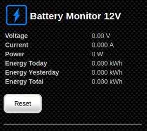
Fig: Integration in your own HTML pages
Integrate measured values in SignalK
The measured values can also be integrated into SignalK and can then be displayed via the instrument panel. How the configuration works in detail is described here:
https://open-boat-projects.org/de/wifi-batteriemonitor-in-signalk-integrieren/
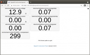
Fig: Measurement data in the instrument panel
Reduce power consumption
The power consumption of the battery monitor can be reduced quite significantly to 1.0 mA at 12 V if the Wemos D1 mini can be switched off using a small switch (red cable 3.3V). The original measuring circuit then continues to run in the switched-off state and counts the power consumption. Only data transmission and display of the measurement data is then no longer possible. After switching on the supply voltage, all data are transmitted again and displayed correctly. This is very useful when you are not on the boat, so as not to discharge the battery.
[back]

Fig: Installation position for the on / off switch
Measurement of the consumption data of the AC shore connection
If you also want to measure the consumption data of the AC shore connection, you can do this with the Sonoff Pow Power Monitoring Switch with the Tasmopta firmware do. The shore connection can also be switched on and off via the module. The newer variant is the Sonoff Pow R2. It has a larger range of functions and can display more measured values and react to limit values. An ESP8266 is already built into these two devices and is only operated with the Tasmota firmware. A modification of the electronic circuit is not necessary as with the battery monitor. The Sonoff Pow R2 is therefore a good addition to the battery monitor.
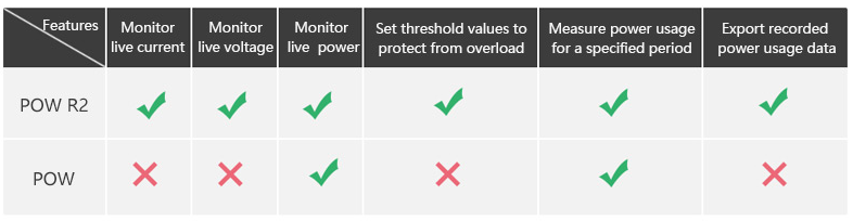
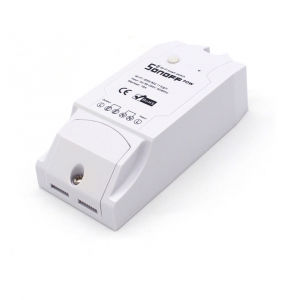
Fig: Sonoff Pow (R2)