We often anchor in Sweden and have been using an anchor alarm on our mobile phones. Unfortunately, this has a few drawbacks: the phone's battery drains quite quickly, and sometimes Android stops the app for some internal reason – especially if it's not in the foreground and the screen is off. Of course, we could also use the alarm integrated into the AIS or the chartplotter, but I find that inflexible and it drains a lot of power from our house batteries.
Therefore, last winter I built a GPS-based standalone anchor alarm as an alternative. It runs on a battery and requires no additional hardware or connections. It has an integrated LiPo battery and an e-paper display. It is controlled by a power-saving ESP32 variant, the Lolin Lite.
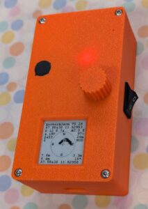
And this is what the device looks like, with a detailed view of the screen in operation:
Components
- Lolin Lite ESP32: optimized for battery operation and quite affordable. In deep sleep mode, this module has very low power consumption, resulting in long battery life.
- 1.54″ e-paper display with a resolution of 200×200 pixels. Sufficiently large for this application, good image quality, and very low power consumption. In deep sleep mode, the last displayed image content remains visible.
- 1800 mAh LiPo battery: sufficient operating hours (at 60 mA average current consumption)
- GPS module (Ublox NEO-6M, NEO-M8N or ATGM336H)
- Optional: active GPS antenna
- Rotary encoder with integrated push button for settings
- Circuit board: I didn't make a separate board for this; instead, I used the circuit board for the e-paper barograph I had previously made. All the necessary pins are available, although not all of them are correctly labeled.
- 3D printed housing made of PLA
Github Repository
All relevant data for the project, including source code, circuit board design and data for 3D printing the housing, will be made available on Github:
Github Repository
It also contains information about the license used for this project.
Using the anchor alarm
The first step is to switch it on using the rocker switch on the side of the device (or to connect it via USB cable).
The device then runs through a few self-tests, including a buzzer. Finally, the main menu is displayed. Turning the knob cycles through the menu items; pressing it selects, adjusts, and exits a menu item.
The menu displays:
- Program Name and Version
- Current GPS position in decimal notation
- Anchor Bearing – Direction to be set from the boat to the anchor in degrees
- Anchor Distance – Distance from the boat to the anchor in meters
- Alert Threshold – A numerical value that determines how often and how far the boat must be outside the "safety zone" to trigger an alarm. For position 10% outside the zone, 1.0 is added to the alarm counter; for position 30% outside the zone, 3.0 is added, and so on. The values are summed, and an alarm is triggered as soon as the alarm counter value exceeds the set "Alert Threshold" value.
As soon as the boat is back within the safety circle, the alarm counter is reset to zero – this prevents false alarms in case of small drifts out of the circle.
The recommended value for "Alert Threshold" is 5; for very sensitive alerting, it should be set to 1.
- Alert Distance – Radius of the safety circle around the anchor in meters
- Sleep time – Time in seconds that the device sleeps between measurements (unless there is an alarm, in which case it is permanently active)
- Detailed Info – Determines in 3 levels how much detailed information is displayed on the screen
- Graph Weight – Determines how thick lines and points are drawn.
- Power Saving Mode – Determines how aggressively power is saved. The medium value „MID“ is recommended.
- Exit: Leave menu and start measurement
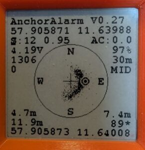
work screen
The work screen, i.e., the page that is active during the measurement, displays the anchor's position as a cross in the center. The safety circle is represented by a circle around the anchor, containing the compass directions.
The boat's current position is displayed as a "target".
Depending on the selected display detail level, further information will be shown:
- Anchor position (top) and ship position (bottom). Previous positions relative to the anchor are shown as points, the size of which depends on the "Graph Weight" setting. This creates a profile during anchoring that shows how the ship has moved around the anchor.
- Number of satellites used and HDOP of GPS
- Accumulated current alarm counter – if this exceeds the "Alert Threshold", the alarm is triggered.
- Activity counter: how often has the device woken up and determined its position?
- Battery voltage and fill level in %
- Distance and bearing from the anchor position to the boat (if the boat is southwest of the anchor position, bearing 235° is shown here)
Alert
The device sounds an alarm if the boat's position is too far from the anchor, or if the battery runs out, or if a valid GPS position can no longer be determined.
Specifically, this means that an alarm is triggered if at least one of the following three conditions is true:
- The boat's current position is too far from the anchor's position. Mathematically:
(Alarm counter) > (Alarm threshold).
The alarm counter is accumulated over multiple measurements: 10% outside the safety circuit adds 1.0, 30% adds 3, and so on. This means that a slight drift only triggers an alarm after several measurements, while a significant drift triggers it quickly. The sensitivity (alert threshold) can be individually adjusted in the menu.
Whenever the boat returns to the safety zone, the alarm counter is reset to zero.
- No valid GPS position for more than 10 seconds. This counter is reset each time a valid GPS position is found again.
- Battery voltage drops below 3.6V or battery charge drops below 10%. Even at excessively low voltage, the device continues to operate until the protection circuit disconnects the battery.
The alarm can be muted by pressing the rotary encoder button; the device will then enter the menu.
Power saving mode
The device is designed for battery operation. To make optimal use of its limited capacity, three power-saving modes are available. The selected mode is set in the menu.
Depending on the GPS module used, the software implements various specific measures:
| mode |
NEO-6M |
NEO-M8N |
ATGM336H |
| MIN |
80 MHz, NMEA Msg, Ped |
80 MHz, NMEA Msg, Ped |
|
| MID |
80 MHz, NMEA Msg, Ped, PSM |
80 MHz, NMEA Msg, Ped, PM2 |
|
| MAX |
80 MHz, NMEA Msg, Ped, PM2 |
80 MHz, NMEA Msg, Ped, HF Off |
|
* NMEA Msg: Disables all unnecessary GPS NMEA messages. Only RMC, GGA, and GLL remain active (CFG-MSH).
* Ped: Switches the GPS module to "pedestrian mode" for better accuracy at low speeds (CFG-NAV5)
* PSM: Switches the GPS module to PowerSavingMode (CFG-RXM)
* PM2: Configured extended power management for a longer update period (CFG-PM2)
* HF Off: Disables the RF section of the GPS module (CFG-RST). Offers the greatest energy savings, but requires time to reacquire satellites.
Reducing the clock rate (80 MHz) reduces the ESP32's power consumption to approximately 75 mA while it is not in deep sleep.
The power consumption of the NEO-M8N is reduced to 45 mA in "MIN" mode and 28 mA in "MAX" mode.
Positioning accuracy is better in MIN mode than in MAX mode – depending on the quality of the satellite data.
Sleep modes and power consumption
The device's power consumption was measured using an FNIRSI FN-058 USB power meter, and the theoretical battery life was calculated for an 1800 mA LiPo battery. Measurements were taken for sleep times of 20 seconds and 50 seconds.
NEO-M8N
| mode |
Power consumption 20s |
Battery life |
Power consumption 50s |
Battery life |
| MIN |
53.0 mA |
33.9 h |
49.2 mA |
36.6 h |
| MID |
39.5 mA |
45.6 h |
38.8 mA |
47.4 h |
| MAX |
43.5 mA |
41.4 h |
36.3 mA |
49.6 h |
The power consumption of the NEO-6M module is somewhat higher, and even higher for the ATGM336H – with correspondingly shorter battery life.
Regardless of the GPS module used, a battery life of 24 hours is guaranteed. With a connected USB power adapter, the battery life is unlimited. Please note: The battery only charges when the device is switched on.
Comparison of the three GPS modules used
NEO-M8N This module appears to be the most suitable of the three GPS modules for this purpose: it has the lowest power consumption, which can be further reduced by its various power management options. It utilizes satellites from the GPS, Beidou, GLONASS, and Galileo constellations – resulting in shorter fix times and improved positional accuracy. It is also the most expensive and the most difficult to obtain.
Please note: In MID mode, this module uses only GPS satellites, with slightly reduced positional accuracy. In MIN and MAX modes, it uses all GPS constellations.
NEO-6M It uses only GPS satellites and has slightly higher power consumption than the NEO-M8N. It also has good power management options. This module is significantly cheaper than the NEO-M8N, readily available, and perfectly adequate if reception conditions are good (i.e., without buildings or mountains nearby obstructing a large portion of the sky).
ATGM336H It utilizes GPS, Beidou, and GLONASS constellations. However, in my tests, positional stability was significantly worse than that of the NEO-M8N. Power management is limited: NMEA messages can be reduced, and the "pedestrian" mode is usable. The supposedly available "power saving" option had no effect for me. Therefore, this module has the highest power consumption of all three GPS modules tested. However, positioning accuracy is good under favorable conditions, such as a clear view of the sky, and when using a well-functioning antenna instead of the included mini-antenna. With the original antenna, the time to acquire a fix can be many minutes, and even after a fix, reception is poor. Prices and availability are comparable to the MEO-6M.
This module usually sees more satellites than the NEO-M8N, however, the positioning accuracy and stability are worse.
GPS Performance
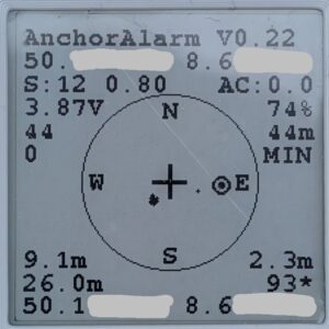
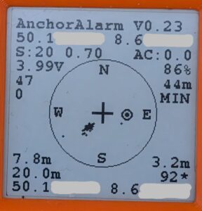
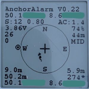
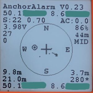
The following images show the GPS performance of the NEO-M8N and ATGM336H modules. The data was recorded in a park with some trees. The time to fix was a few seconds in each case. Power saving mode "MIN" was used for the images in the first row, and "MID" for the second row. After a few minutes of measurement, I moved approximately 20 meters further to move the ship symbol away from the data points.
The NEO-M8N limits itself to 12 satellites, while the ATGM336H uses as many satellites as it can receive. For both modules, the results are excellent in "MIN" mode, with a slightly wider distribution for the ATGM336H. The distribution is somewhat broader in "MID" mode, but still quite good.
The numbers in the 3rd row from the bottom show the standard deviation of the data points in the X and Y directions.
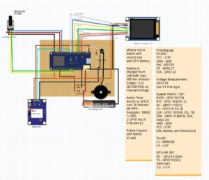
Circuit diagram
The circuit diagram is currently available as a Fritzing file.
Pin assignment of the assemblies
KY-040 Rotary Encoder
| VCC |
3.3V |
| GND |
GND |
| SW |
GPIO 26 |
| DT |
GPIO 27 |
| CLK |
GPI 22 |
Voltage measurement
The battery voltage is measured at GPIO 39 via a resistor bridge with two identical resistors of approximately 200 kOhms, which reduce the measured voltage by half.
ePaper module
| BUSY |
GPIO 04 [15] |
| RST |
GPIO 16 [RES, 2] |
| DC |
GPIO 17 [D/C] |
| CS |
GPIO 05 [SS, 4] |
| CLK |
GPIO 18 [SCK, SCL, 18] |
| DIN |
GPIO 23 [MOSI, SDA, Data/ 23] |
| GND |
GND |
| VCC |
3.3V |
Buzzer
An active buzzer is used for alarm notification. The buzzer's positive terminal is connected to the supply voltage (3.3V), and the negative terminal is switched through an S8050 switching transistor. GPIO2 of the ESP32 is used to activate the buzzer; it is connected to the transistor's base (pin 2) via a 2kΩ resistor. Pin 1 (C) of the transistor is connected to GND, pin 2 (b) to GPIO2 via the 2kΩ resistor, and pin 3 (E) to the buzzer's negative terminal.
| Transistor base |
via 2 kOhm -> GPIO2 |
GPS module
Communication with the GPS module is via a serial interface. RX = GPIO15, TX = GPIO19. On the circuit board used, GPIO15 is labeled "SDA" and GPIO19 is labeled "SCL".
| RX |
GPIO15 (SDA) |
| TX |
GPIO19 (SCL) | |
| GND |
GND |
| 3.3 |
3.3 V |
circuit board
I didn't design a new circuit board for this device; instead, I reused one I had previously used for a barograph. All the necessary GPIOs and connectors are available, although not all are grouped or correctly labeled.
- ePaper: connected as intended
- Buzzer: connected as intended via an S8050 transistor. Its base is connected to GPIO2 via a 2kΩ resistor.
- NEO-6M GPS Module: the pins originally intended for I2C are used (3.3V, GND, GPIO 15 (SDA) and GPIO19 (SCL))
- KY-040 Rotary Encoder: is connected to 3.3V and GND via OneWire connector, and to GPIOs 22, 26 and 27 via the unlabeled spare pins on the left side of the Lolin Lite board.
casing
The housing, including the rotary knob, is 3D printed in PLA. The STL file for this is available in the GitHub repository. Please note: the file contains several parts that must be separated by the slicer before printing.
Limitation of liability
This project is a hobby project and is provided for demonstration, testing, and training purposes. All hardware designs, software, firmware, and documentation are provided "as is," without any express or implied warranties or guarantees of specific functionality, and without any representations regarding merchantability or freedom from third-party rights. The authors and contributors are not liable for any direct or indirect damages, including damage to property, data loss, personal injury, fire, electrical hazards, or other legal consequences arising from the use, misuse, or inability to use this project. This project is not intended for use in safety-critical, medical, mobile, industrial, or commercial environments. The user is solely responsible for ensuring the correctness, safety, and applicability of this project for their intended use and for ensuring compliance with all applicable laws, regulations, and standards. Use of this project is at the user's own risk.