First, a few important notes that you should definitely observe.
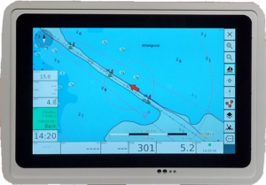
Fig. 10″ Plotter OBP 10.1 AvNav
Table of contents
- 1 introduction
- 2 kit
- 3 processor boards
- 4 Hardware recommendation processor board
- 5 Raspberry Pi Compute Module CM4
- 6 SSD storage
- 7 External SSD storage
- 8 SD card and USB memory
- 9 processor cooling
- 10 WiFi
- 11 Download and configure AvNav Image
- 12 Copy AvNav to the storage medium
- 13 Preparations assembly
- 14 Mechanical assembly
introduction
Already at Boot 2020, Christian has the first approach to a 10″ homemade plotter undertaken at the end of 2021 to develop a 7″ version led. In the meantime, however, some aspects of these concepts have turned out to be impractical. In particular, the use of a Raspi Compute Module CM3 and its discontinuation had brought the development line into serious difficulties. The base board would have had to be completely redesigned to adapt to other hardware.
In 2022, the development of the 10″ plotter presented here followed, which was improved in a few points compared to the 7″ version. The layer concept for the structure was adopted and reduced to just one layer, which was easily implemented with a new housing from Bopla. By using a touch display and adding a remote control, the keyboard could be omitted. The only control element on the device is an on/off switch. This significantly simplifies the construction and there are fewer problems with assembly and water resistance. It has also turned out that OpenCPN cannot be operated well with the keyboard. Therefore, now only AvNav supported, which is ideal for touch operation and remote control.
The plotter is designed for integration into a WiFi network. In regular operation, this applies to the display of NMEA data from the on-board network (plumb, log, wind, AIS...), the output of data (autopilot control) and, for example, operation via a tablet or notebook at the chart table. But a connection to the outside world is also indispensable for map or software updates, importing waypoints and routes or downloading tracks. Standalone use is not impossible, but leaves many of these options unused.
The connection to the existing on-board electronics - be it individual devices or a network - can be made using commercial hardware (here is an overview) or via this one Open Boat Project The plotter itself can act as an 'access point' to provide a WiFi network for other devices or connect to an existing network as a 'client'.
kit
Christian has launched a first small series as a kit for the 10″ plotter. Most of the required parts are included, which makes assembly much easier.
- 10″ touch display with control
- Acrylic cover plate
- Machined case
- Raspi HAT
- GPS receiver
- speaker
- IR receiver with remote control
- Labeling foils and seals
- bolts, screws and nuts
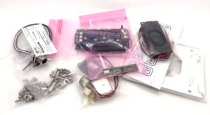
Fig.: Parts set
The CPU board and some other things need to be taken care of by you. All kits are currently sold out. Due to popular demand, there will be more kits in the future. If you are interested, please contact us via this contact form.
Before you assemble the plotter, you should consider what your usage scenario looks like. Due to the many possibilities of using a wide variety of hardware, there are different ways of implementing the project. The biggest hurdle at the moment is getting a Raspberry Pi. Not everyone will be able to get the best hardware and you will have to live with a few compromises. Our current hardware recommendation consists of the following components:
- Waveshare Mini Base Board B
- CM4 Compute Module with 4GB RAM and Wifi (with or without eMMC)
- Processor fan for CM4 module
- 128GB SSD
- WiFi planar antenna in housing
- 10″ touch screen
- Bopla housing for 10″ displays
- IR remote
- External LTE router for internet connection (optional)
If you decide to use a different piece of hardware, it can get a bit more difficult at some points during commissioning, because you have to install drivers on the Linux console, for example, or you have to make some other settings directly under Linux. This requires a certain knowledge of Linux and the willingness to deal with software problems. With this description we have tried to show as many typical hardware constellations as possible. If that doesn't help you, feel free to post your questions and suggestions in the sailing forum. We have an extra one own area set up for it. Get an overview of solved problems before asking new questions in the forum. If you have found solutions to your own problems, we ask that you also share them in the forum. This way others can benefit and save a lot of time and frustration.
In order to successfully implement the project, you should have technical skills and basic knowledge of Linux. The project is not plug & play and requires some familiarization with the subject in some areas. In the forum you will find some sailors who are doing the same project and are friendly and helpful. This way you are not alone with your questions and can find solutions together. In the end, you will be rewarded with a plotter that is very customizable to your needs and you understand how it works. In addition, we would of course be happy to receive any form of feedback.
processor boards
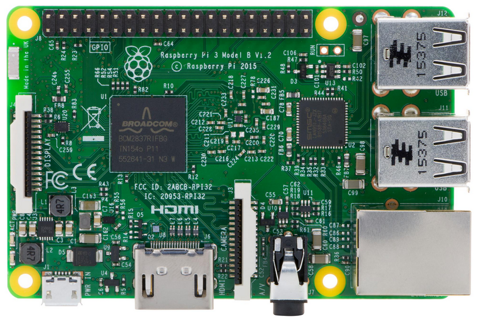
The base is a Standard Raspberry Pi 4B intended. It already has all the essential functions on board and the wide distribution makes it easier to use for other functions.
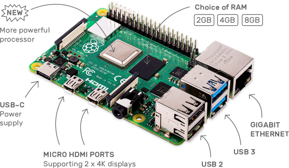
Fig: Raspberry Pi 4B (Raspberry Pi Foundation)
The procurement of a Raspberry Pi 4B is currently - early 2023 - difficult. According to statements by the Raspi Foundation, the situation should improve in the first quarter of '23, but this is not yet apparent. In the meantime, some competitors have recognized a gap for themselves and are offering alternatives that are better available Raspberry Pi Compute Module 4 (in short: CM4 module) and have a significantly better equipment. A few other competitors, on the other hand, rely on processors that are easier to obtain.
wave share eg puts on Mini base boardsthat can accommodate a CM4 module. In addition, the base board houses a real-time clock and an SSD adapter for M.2 modules, which are not available on the Raspberry Pi 4B. This makes the Mini Base Board from Waveshare very interesting for use in the 10″ plotter, since the SSD is finally a permanently writable medium. With the Raspberry Pi 4B, this has to be implemented in a complex manner using external modules.
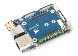
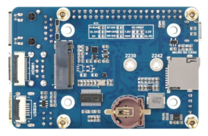
Fig.: Mini Base Board B, top and bottom
There are also adapted speed-controlled fans for the Mini Base Board B with CM4 module, which are very practical and are not significantly higher than the Ethernet socket on the board.
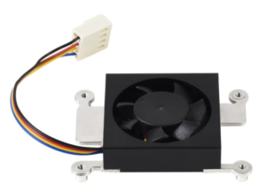
Fig. Fan for CM4 module
Radxa
The company Radxa offers with the skirt 4 a board that is similar to the Raspberry Pi 4B, but uses a different processor. It is the OP1 64-bit hexa-core processor with Dual Cortex-A72 and Quad Cortex-A53. The processor is roughly equivalent to the Raspberry Pi 4B, but uses the Raspberry Pi B3 format for the interface arrangement. This should make all older cases usable. With the pin assignment of the 40-pin connector, almost all signals are in the same place as on the Raspberry Pi 4B. This should also work with the majority of the available HATs with the board.
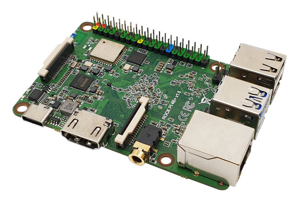

Fig.: Radxa Rock Pi 4, top and bottom
The Radxa Rock 4 also supports SSD modules in M.2 format and would therefore be a promising candidate for the 10″ plotter. When using an SSD, however, it is not possible to use a CPU cooler. Whether the cooling concept is sufficient and the Radxa Rock Pi 4 runs with the AvNav Image still has to be checked. It may well be that some adjustments are still necessary. There is currently no hardware recommendation for this board.
Hardware recommendation processor board
The boards in the following table can currently be used as processor boards for the 10″ plotter. You can achieve the best results with a Waveshare Mini Base Board B, a CM4 module with 4GB RAM and WiFi/BT, and an SSD storage medium.
| processor board | Furnishing | boot medium | comment |
Waveshare Board B with CM4 module |
2x USB3
1x HDMI 1x network 10/100/1000 1x M.2 NVMe SSD 2230, 2242 1x microSD card 1x RTC with battery 1x fan connector regulated |
M.2 NVMe SSD
microSD card via USB adapter |
Current reference implementation
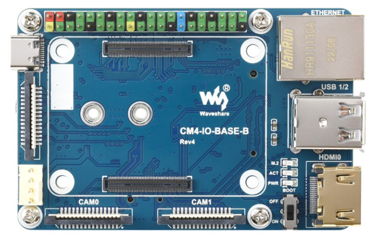
Not bootable directly from microSD card if the CM4 eMMC contains memory 2x USB2 and 1x HDMI via external adapter board fan necessary WiFi and BT via CM4 module or USB |
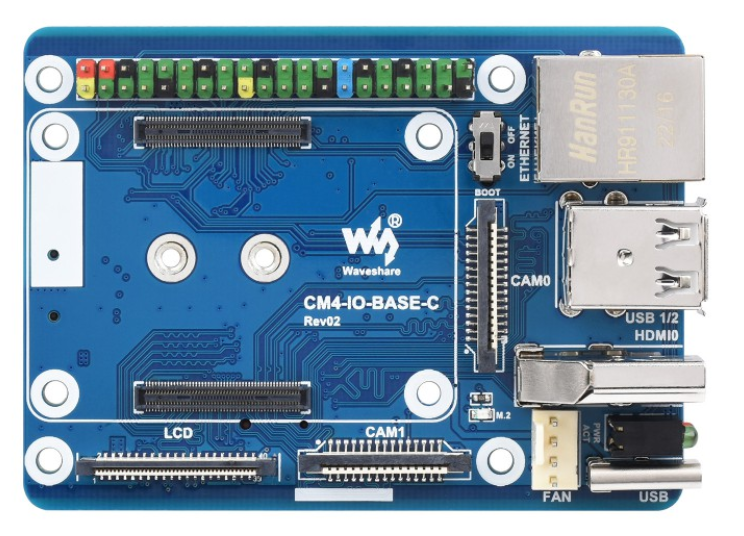
Waveshare Board C with CM4 module |
2x USB3
1x HDMI 1x network 10/100/1000 1x M.2 NVMe SSD 2230, 2242 1x microSD card 1x RTC with battery 1x fan connection unregulated |
M.2 NVMe SSD
microSD card via USB adapter |
Not bootable directly from microSD card if the CM4 eMMC contains memory
CM4 with at least 4GB RAM fan necessary, Audio cannot be used with fan control via GPIO18 WiFi and BT via CM4 module or USB |
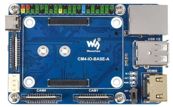
Waveshare Board A with CM4 module |
2x USB3
1x HDMI 1x network 10/100/1000 1x M.2 NVMe SSD 2230, 2242 1x microSD card 1x fan connection unregulated |
M.2 NVMe SSD
microSD card via USB adapter |
Not bootable directly from microSD card if the CM4 eMMC contains memory
2x USB2 and 1x HDMI via external adapter board fan necessary WiFi and BT via CM4 module or USB No RTC included |

Raspberry Pi 4B |
2x USB2
2x USB3 2x mini-HDMI 1x network 10/100/1000 1x microSD card 1x WiFi 2.4GHz 1 x Bluetooth |
microSD card
SSD via external USB housing possible |
SD card prone to defects in continuous operation
Fan installation difficult At least 4GB RAM weak WiFi performance due to on-board antenna |
Raspberry Pi 3B |
4x USB2
1x HDMI 1x network 10/100/1000 1x microSD card 1x WiFi 2.4GHz 1 x Bluetooth |
microSD card
SSD via external USB housing possible |
SD card prone to defects in continuous operation
Fan installation difficult At least 4GB RAM weak WiFi performance due to on-board antenna |
Raspberry Pi Compute Module CM4
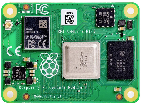
Fig.: CM4 module Lite with WiFi, without eMMC

Fig.: CM4 module with WiFi and eMMC
CM4 modules are required for the Waveshare boards. All important hardware components are located on the module in a very compact form, but without directly usable connections. On the underside there are two sockets to the base board, which in turn provides the usual interfaces to the outside world. These modules are available in various designs. The following modules can be used for the 10″ plotter:
| R.A.M. | eMMC | WiFi / Bluetooth |
| 1GB 2GB 4GB 8GB |
without 8GB 16 GB 32GB |
With without |
The modules are available in 32 different versions, but not every supplier offers them. In principle, care should be taken to order a module with sufficient memory. 1GB RAM is clearly not enough memory. 4GB or larger is recommended. AvNav also runs with 2GB, but the memory is very tight if further applications are to be added to the module later. Whether you order a module with or without eMMC memory is completely irrelevant. In most cases, modules with 4GB RAM can only be ordered with eMMC memory. If there is eMMC memory on the CM4 module, the memory slot for the microSD card on the Waveshare Boards A/B/C can no longer be used because the eMMC memory replaces the SD card. In principle, AvNav can also be installed on the eMMC memory. However, like the SD card, the eMMC memory is not suitable for permanent write operation as with an SSD. The use of the eMMC for AvNav is therefore not recommended. For long-term use, AvNav should be installed on an SSD. It is also significantly faster than an SD card. If you absolutely want to use an SD card, you should expect that the SD card will become slower in data access after a while because wear leveling replaces memory cells that have been written to be broken with others. The effect only occurs after some time and makes AvNav noticeably slower to use. A functioning backup is absolutely necessary in order to remain operational in critical situations.
If possible, you should buy a module with WiFi and Bluetooth right away, since the CM4 module has an antenna plug for a WiFi antenna, so you can attach the antenna to an optimal position in the housing. Also buy the WiFi antenna for the CM4 module from the dealer. If you buy a module without WiFi and Bluetooth, you can retrofit WiFi via WiFi USB modules. However, Bluetooth is not supported. That has come to be recommended Edimax WiFi Adapter N150 proven. If you order other WiFi USB modules, you should make sure that they are supported under Linux in the Raspberry. You may have to add the necessary drivers yourself. It is best to follow our recommendation to avoid problems when setting up WiFi. However, when using a WiFi USB module in the USB slot of the base board, you must expect that the WiFi range and the connection quality will be limited compared to a remote and optimally placed antenna. A USB extender allows you to use a more convenient location in the case.
SSD storage
If you use a Waveshare board with a CM4 module, you can use SSD M.2 NVMe memory cards. When buying, pay attention to the format M.2 and NVMe. Other modules with NGFF/SATA are also offered, which look identical but cannot be used. Below you can see SSD memory in M.2 format that you can use.
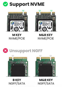
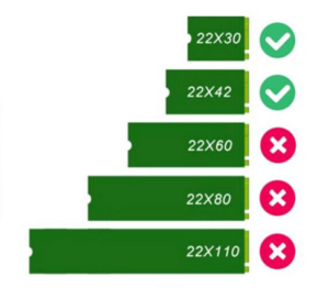
Fig.: SSD M.2 NVMe storage
Only modules with a length of 30 and 42 mm can be used in the Waveshare Board. You can currently find modules with 64…512 GB. modules with 128GB currently offer the best price/performance ratio.
When installing the module, ensure that the module is correctly aligned and do not insert it the wrong way around. The fixing screw supplied with the Waveshare board is too long and will damage the CM4 module on the back when screwed in completely. In any case, use a suitable M3 washer or a toothed washer and check the seat of the screw on the opposite side if the CM4 module is not installed. With some SSD modules, the screw head touches the memory chip on the M.2 module and can damage it. Check this situation as well and use a different screw if necessary.
External SSD storage
Who an SSD with a Raspberry Pi 3B or 4B want to use, can eg external SSD housing for M.2 NVMe modules use. When buying the external SSD housing, make sure that you also buy the matching M.2 modules. SSDs with a length of 60 mm can also be used in these modules. To connect to the Raspi board, you also need a USB-A to USB-C adapter cable.
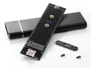
Fig.: External SSD housing
The circuit board can also be attached to the mounting frame in the plotter without its own housing. Make sure that the circuit board is held securely in the long term to avoid unwanted short circuits.
External SSD enclosures for M.2 NVMe modules can also be used perfectly to copy the AvNav image to an M.2 NVMe module. So you can also perform the copying process on Windows and macOS.
SD card and USB memory
A microSD card can also be used for the operating system and AvNav. The kits is one SD card already settled. As described above, an SD card is not an ideal storage medium for permanent write operation, as occurs under Linux. Expect noticeable responsiveness degradation over time. It is best to use high-quality ones SD cards with SDHC Class 10 renowned memory manufacturer such as SanDisk. Prefer the highest possible write and read rates in order to be able to access the memory quickly. Memory larger than 32 GB is not supported by the CM4 module or the Raspberry Pi.
If you are using a CM4 module with eMMC memory, the SD card slot on the Waveshare Board cannot be used. If you want to boot from an SD card, you need an SD card USB adapter. These adapters are very compact and can be used directly in the USB port of the Waveshare board. The SD card is pushed into the narrow slot of the connector at the bottom. The advantage of such adapters is that you can determine the quality of the SD card used yourself and have the option of transferring the AvNav image to the SD card via a PC.
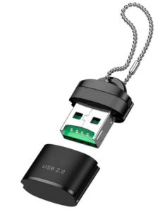
Fig.: SD card USB adapter
Alternatively, mini USB sticks could also be used, which have similar dimensions to an SD card USB adapter. However, the quality of the mini USB sticks is difficult to determine, since a large number of such sticks are offered by different manufacturers. When using these sticks, you must first install AvNav on the mini USB stick.
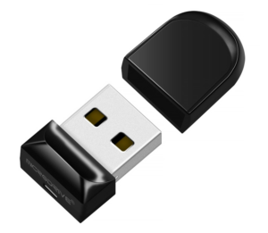
Fig.: Mini USB sticks
As a last resort, ordinary USB sticks can also be used, which are used with a USB extension on the board's USB port and are securely fastened to the carrier board.
processor cooling
Fig.: CM4 processor cooler from Waveshare
The processor must be cooled during operation in the plotter. Make sure you have sufficient processor cooling to avoid problems due to hardware failure or performance losses. Excellent cooling is available with the Waveshare Board B and associated Processor cooler for the CM4 module given. A 5V connection is already available on the Waveshare board, with which the cooler can be operated with temperature control.
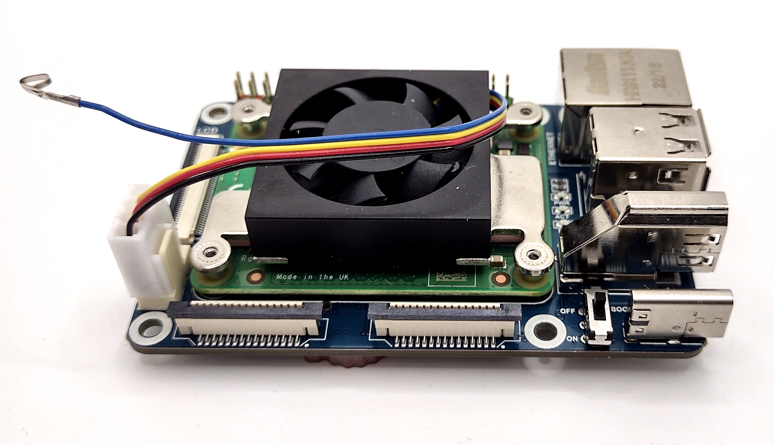
Fig.: Mounted heat sink with fan on Waveshare Board C
Speed control wire (blue) disconnected
Care should be taken when using the Waveshare Board A or C. No chip for temperature control is installed on this board and the PWM signal for speed control is provided by the software via GPIO18. Since GPIO18 is also required for the audio output, you have to do without the audio output. If you don't want to do without it, you can alternatively unclip the plug insert of the blue cable from the fan connector and pull it out. To do this, use a needle and push the pawl of the plug insert back slightly. Then insulate and attach the folded-back connector insert to the ribbon cable. The fan then rotates at maximum speed. However, the fan noise is not significantly louder than with a regulated fan.
Alternatively, GPIOxx can also be used for fan control. In order for this to be possible, you must pull out the blue cable from the fan connector and connect it to pin xx of the 40-pin. Connect connector strip. You also need a Python script that provides a PWM signal for speed control via software. This script must be configured to start automatically on boot. The method is only recommended for advanced users with experience. For everyone else, the previous two methods of processor cooling are recommended.
Raspberry Pi cooling
For the Raspberry Pi 3B/4B, there is no such simple CPU cooling method as the CM4 module. Here you have to help yourself individually and find your own solutions. One possibility would be to glue a heat sink to the CPU and blow air in from the side with a radial fan.
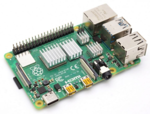
Fig.: Raspberry Pi 4B with heat sinks
WiFi
When using a Raspberry Pi or a CM4 module with WiFi, AvNav can be set to work as a WiFi access point, or it can be connected to another WiFi network as a client. The operating mode is configured via the web configurator. The WiFi network works in the 2.4 GHz range and supports 802.11 bgn. This enables data transfer rates of up to 150 MBit/s, which corresponds to around 15 MB/s. However, the data transmission rate depends on the antenna used and the utilization of the radio channel. In crowded ports with a lot of WiFi operation in the 2.4 GHz range, the data transmission rate can drop significantly and sometimes also cause disconnections. The small print antennas on the Raspberry Pi 3B/4B boards are not particularly well suited to connecting to a port WiFi network. If you need good connection quality, you should rely on powerful external antennas and make sure that the antenna height is sufficient.
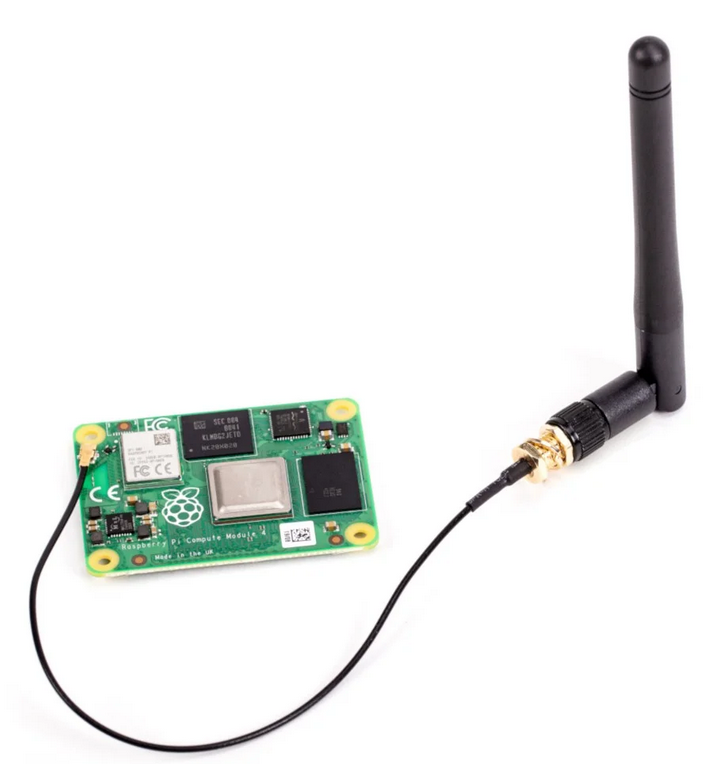
Fig.: External WiFi antenna on the CM4 module
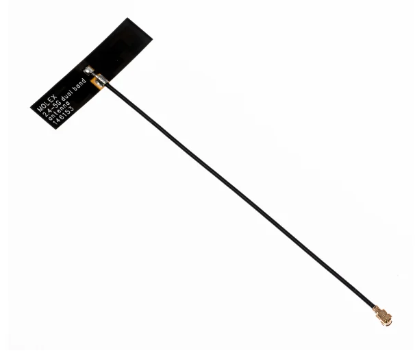
Fig.: Planar antenna for CM4 module for internal installation
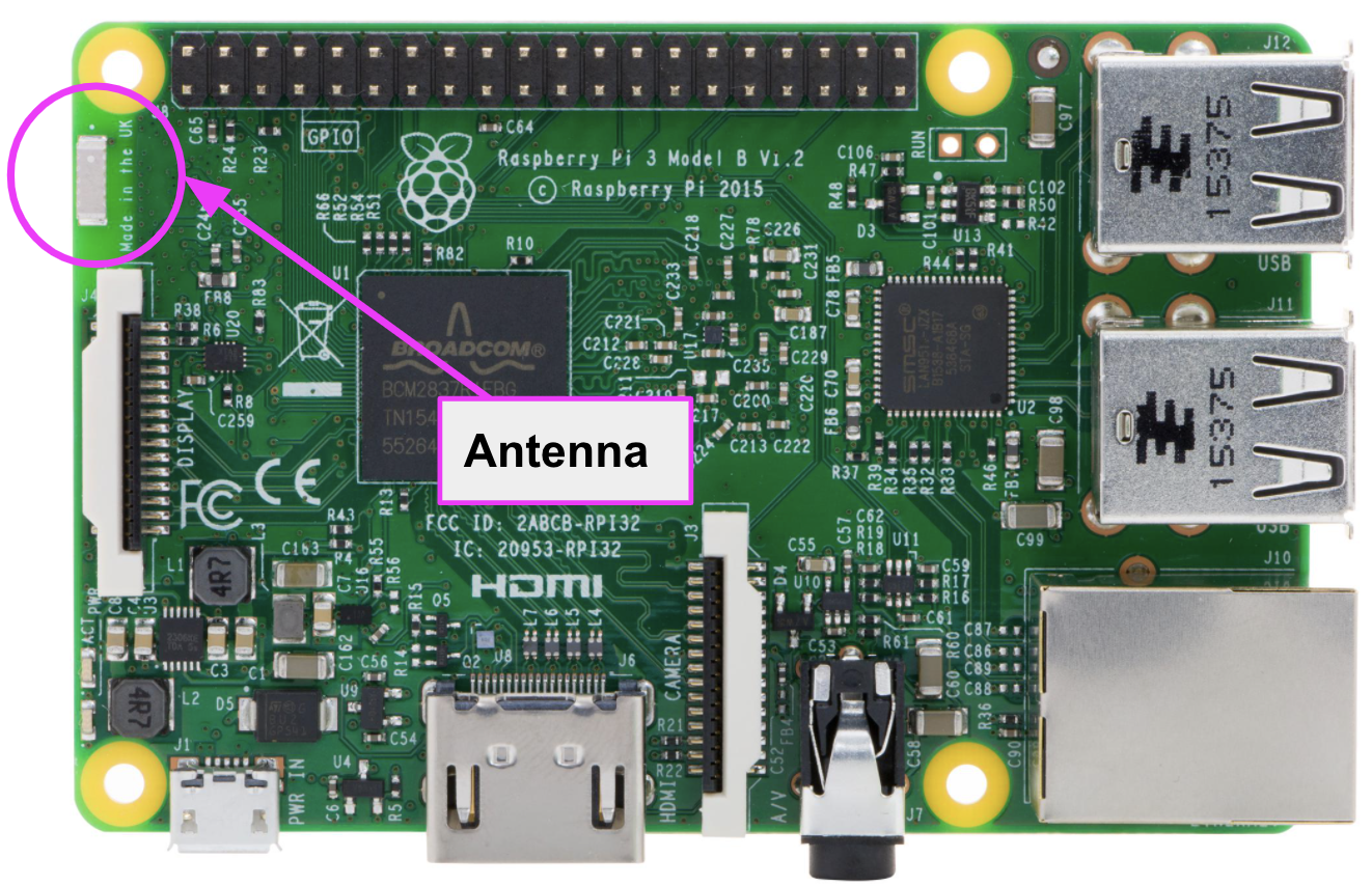
Fig.: WiFi antenna Raspberry Pi 3B
With the CM4 module with WiFi, it is possible to connect an external antenna, which is either installed in the housing or is routed to the outside via a connection. If you want to work with external antennas on the Raspberry Pi 3B/4B, you can do this using a WiFi USB stick that has a connection for an external WiFi antenna.
WiFi access point
At AvNav, the WiFi access point is realized with the WiFi chip on the board. Should the configuration be set to WiFi client, then the WiFi chip takes over the client connection to an external WiFi network. In this case, the access point is switched off. If you still need a WiFi access point, you have to use a USB WiFi adapter. Consult the beforehand compatibility list for Debian and see if the adapter is also suitable as an access point. Because not all adapters support the AP mode under Linux.
Two independent WiFi networks can be operated in AvNav. AvNav can be connected to the port WiFi at the same time and pass the internet connection through to other WiFi devices via the access point. However, it should be noted that there is no intervening firewall, which means that you are exposed to an increased security risk. As long as AvNav is operated isolated from the Internet, the access point poses no risk.
If you want to operate a permanent Internet connection on board, you should get an LTE router with an independent access point. AvNav is then connected to the LTE router as a client. All other devices such as mobile phones, tablets and laptops are then also connected to the LTE router and can exchange their data with each other. Due to the built-in firewall in the LTE router, the devices cannot be accessed and attacked on the Internet. Security is significantly higher than with a direct connection to the Internet. You also avoid the problem of finding a suitable USB WiFi adapter that can also be used as an access point.
WiFi client
AvNav can also be operated as a client. In the Web configuration is the option Internal WiFi as client to activate. The WiFi chip on the board then takes over the connection to the external WiFi network. A previously activated WiFi access point is then switched off unless another USB WiFi adapter is used. The client connection parameters are set directly in AvNav via the interface.
If you use a CM4 module without WiFi in connection with a Waveshare Board, you can establish a client connection with a USB WiFi adapter. Be sure to plug the USB WiFi adapter into the xxxx port. On the other port it cannot be used as a WiFi client.
There is a ready-made AvNav image for the 10″ plotter. This image contains all the necessary software extensions to be able to control the complete hardware of the plotter:
- display control
- Touch sensor for display
- Adaptive display brightness
- sound output
- IR remote
- RTC
- fan control
- GPS receiver
- CAN driver for NMEA2000
- USB driver for NMEA0183
- WiFi support
It's not worth setting up your own Linux for AvNav. The effort is immense and if there are problems, you have to find solutions yourself. Please understand that we can only provide support for the AvNav Image that we provide. Problems with modifications to the image that you have carried out yourself must be rectified by you.
The AvNav Image consists of two parts. The first part is the image itself, the second part is a configuration file. Both parts must be downloaded separately and later transferred to the storage medium.
The AvNav Image is available in two versions, a 32-bit version and a 64-bit version. Load the image for your respective hardware as 32bit version Download and save the zip file on the PC. The 64-bit version is also possible, but we expressly recommend the 32-bit version.
| image version | hardware |
| 32bit version | Waveshare board with CM4, Raspberry Pi 4B, Raspberry Pi 3B |
| 64bit version |
Waveshare board with CM4, Raspberry Pi 4B, Raspberry Pi 3B |
AvNav is configured on the plotter hardware via a web-based configuration page outside of the Raspi board on a PC. The hardware components are selected and configured there. The configuration page can be accessed via the following link:
Make the following settings for the 10″ plotter:
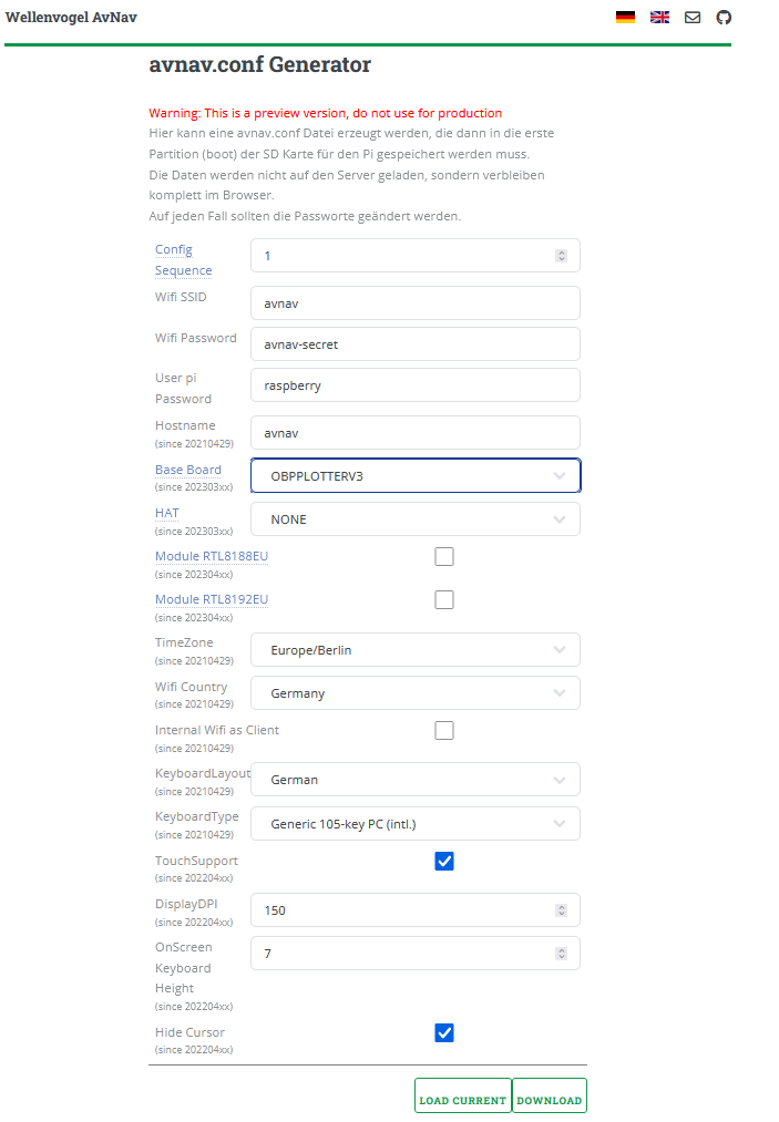
Fig.: AvNav configurator (click image to enlarge)
Entries 2…5 can be customized. When entering special characters, make sure that they correspond to the ASCII character set are equivalent to. Otherwise you may not be able to log into the system. At the end of the configuration you can use the button Download a file named avnav.conf download. This file is then later added to the AvNav image on the storage medium.
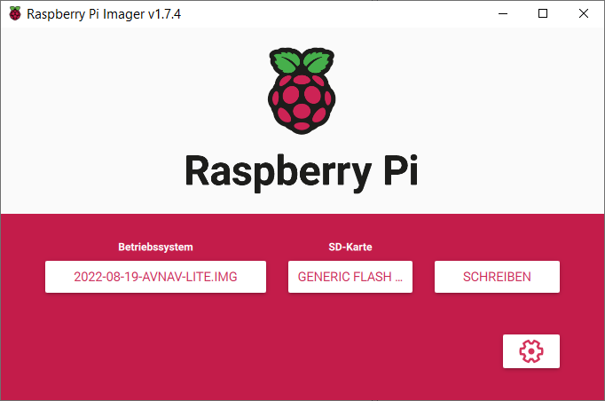
The installation of AvNav is always done with the Raspberry Pi Imager performed. The imager formats the storage medium, copies the unpacked AvNav image onto it and sets it up to be bootable. In the last step, the AvNav configuration file is added to the storage medium.
The Raspberry Pi Imager for Linux, Windows and macOS can be downloaded from the following link:
https://www.raspberrypi.com/software/
After the installation you can start the Raspberry Pi Imager.

Fig.: Raspberry Pi Imager
The AvNav image is provided as a zip file and still needs to be unpacked. The unzipped file should be a file named xxx-anvan-xxx.img be visible. This file contains the Linux operating system and the necessary software for AvNav and is required for the Raspberry Pi Imager.
To copy AvNav to an SD card or a USB memory stick, connect the storage medium to your PC. Make sure the media is erased and freshly formatted in FAT32. You should then see your storage medium as a separate drive in the file tree.
In the Raspberry Pi Manager, select using the button select OS -> Own image the operating system by clicking on the image file xxx-anvan-xxx.img refer. As SD card select the drive under which your storage medium can be found. The storage medium should have at least 4GB memory size.
After that, press Write. The image is now written to the storage medium. Depending on the size of the medium, this takes about 2…5 minutes.
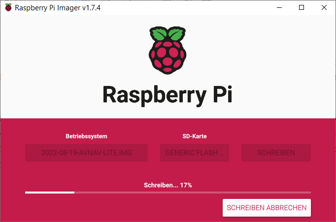
After the copying process, the image is checked again and the whole process is complete.
Copying AvNav to an SSD can be done in two ways. Either via a external SSD housing for M.2 NVMe modules or via a USB connection to the Raspi board. The variant with the external SSD housing is quite simple and you can follow the instructions like copying to an SD card. It is suitable for Linux, Windows and macOS and does not require any special software preparations.
Fig.: External SSD housing
The second variant via a USB connection with the Raspi board is only intended for Waveshare boards with a CM4 module and only works under Linux. You need the program for that usbbootthat you have to compile beforehand on your Linux PC and then run it on the PC. The Waveshare Board with CM4 module and activated boot mode must be connected to the Linux PC with a USB cable. usbboot is started on the Linux PC and loads a minimal Linux into the Raspi via USB, with which it behaves like a USB memory stick. After that, you will see several drives that correspond to the respective memory types (SD card, EEPROM, SSD). With the Raspberry Pi Imager the image is then transferred to the Raspi like an SD card to the SSD. In order for the whole thing to work, however, the CM4 module must contain the correct bootloader that can boot from USB and SSD. The bootloader on some CM4 modules is partly too old and needs to be updated because booting from SSD is not possible. usbboot contains all necessary programs. The following describes how to update the bootloader and how to put the Raspi board into USB memory mode using the CM4 module. The starting point is the home directory. The Waveshare Board must be connected to the Linux PC via a USB cable at the USB-C socket. The plug of the USB-C socket must click into place. Otherwise you cannot connect to the board. The PC must provide at least 500 mA current so that the Raspi can start. In addition, on the board the boot switch on on be set. A jumper must be set on some boards.
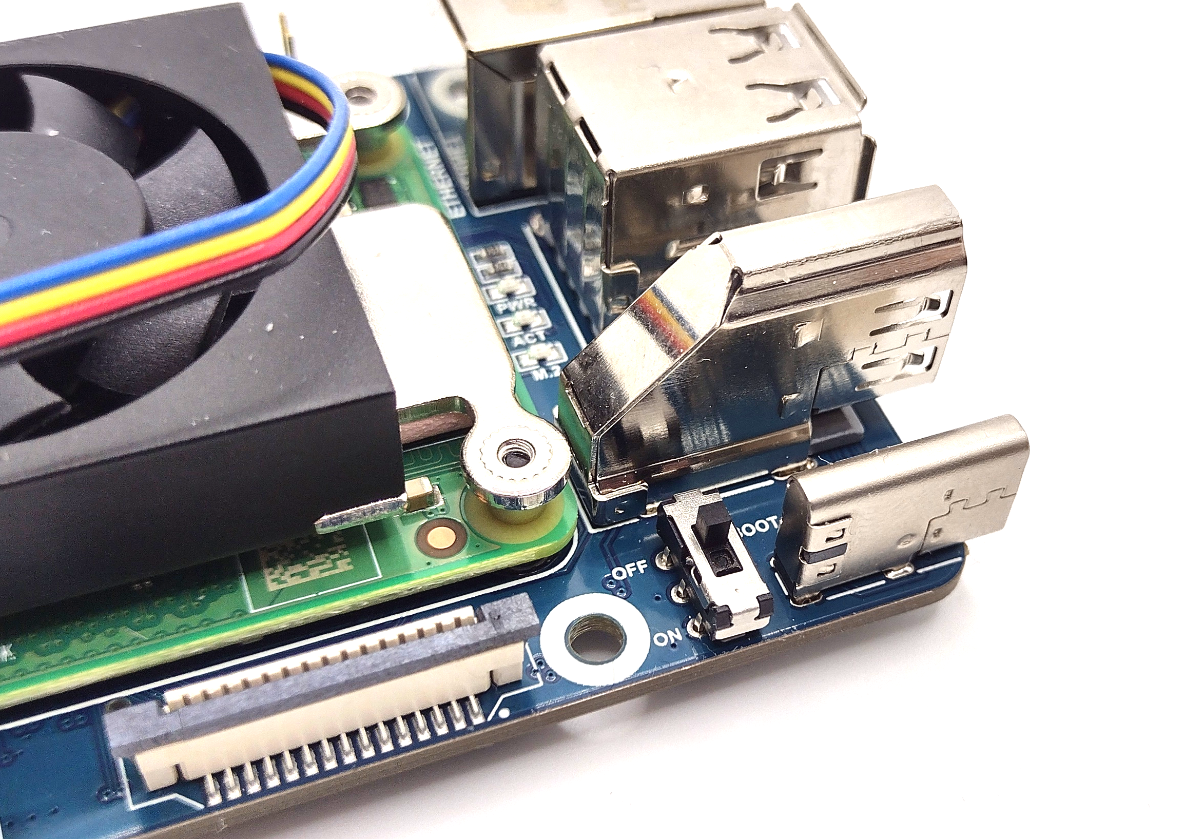
Fig.: Boot switch
Then the following steps are to be carried out or the italic Enter the written commands in the Linux terminal window:
- boot switch on on ask and board over the Connect the USB-C socket to the PC
- Download git:
sudo apt install git libusb-1.0-0-dev pkg-config - Create directory usbboot:
sudo mkdir usbboot - Change to the usbboot directory:
cd usbboot - download usbboot:
git clone –depth=1 https://github.com/raspberrypi/usbboot - Compile software:
make - Update bootloader:
sudo ./rpiboot -d recovery - Unplug the USB cable from the PC and plug it back in for a reboot
- Transfer USB connection software to Raspi:
sudo ./rpiboot -d mass-storage-gadget - Check whether the Raspi can be seen as a USB device:
lsusb - Check which drives are visible:
sudo dmesg - Transfer AvNav with the Raspberry Pi Imager as with the SD card (nvme0n1 – SSD, mmcblk0 – eMMC)
- Unplug the USB cable from the PC and boot switch on off place
Detailed terminal outputs are here to find. If a storage medium was already formatted in step 9, all available drives such as SSD, eMMC and SD card are displayed in the Linux file manager and opened automatically. If nothing opens automatically, none of the available drives are formatted. Then you can check in step 10 whether the Raspi board can be seen as a USB device at all. You should find a message like this:
Broadcom Corp. Raspberry Pi multi-function USB device
In step 11 you can see in detail which drives are available and which names are assigned to them:
scsi 8:0:0:0: direct access nvme0n1 (SSD NVMe)
scsi 7:0:0:0: direct access mmcblk0 (if eMMC is present on CM4)
stand by nvme0n1 for an SSD and mmcblk0 for an eMMC memory. The memories in the Raspberry Pi Imager can be addressed under these names and are displayed under the point CHOOSE SD CARD selected. AvNav is transferred in the same way as with an SD card.
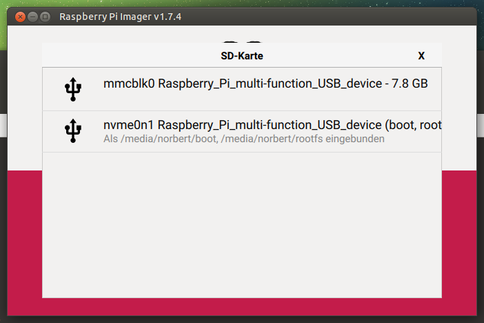
Fig.: SSD and eMMC as installation drives
After successful transfer, unplug the USB cable and insert the boot switch up again off return. Next time, the Raspi will start from the storage medium that it finds first. The boot order of the storage media is set as follows:
boot order
- SD card slot / eMMC
- Storage medium to USB-A
- SSD NVMe
- Storage medium on USB-C or on USB-A with the CM4
- network
- reboot
If no bootable storage medium is found, the Raspi performs a reboot and checks all storage media one after the other. If your CM4 module already has a bootable image in the eMMC memory and you want to use an SSD, you must remove the image from the eMMC. You can do this by repeating step 9 and deleting all partitions of the eMMC drive with GParted. If you don't do this, the eMMC will always boot even though there is a bootable SSD.
If you want to change the boot order, you can switch to the subdirectory ../usbboot/recovery on the PC and edit the boot.conf file and then update the boot loader on the CM4 module again. information about Setting the boot order can be found at the link.
In principle, the eMMC memory can also be used as a boot medium with the method described. However, we expressly advise against it, since eMMC memory is not designed to be continuously writeable. If the eMMC memory is defective, you have no way of replacing the memory. Then use removable SD cards instead.
Add configuration file to storage medium
Preparations assembly
First, a few tips that you should consider when using screws in plastic. Plastic screws are designed in such a way that they can cut their own thread into the plastic. Screwing screws into plastic with an existing thread should be done in such a way that the screw is applied and first turned to the left until you feel it click into place. At that moment, the thread of the screw is in sync with the thread in the plastic. Only then can the screw be turned to the right. If you ignore this, the existing thread in the plastic can be destroyed. Do not overtighten the screw. Otherwise you can overtighten the thread and the screw will no longer hold. The instructions apply in particular to the housing. In order to meet waterproofing requirements, the screws must securely press the case gasket.
The construction concept is based on the proven construction with layers on which the components are attached. With the 10″ plotter there is only one layer. The processor module, i.e. the Raspberry Pi 4 or the Waveshare Mini Base Board with CM4 module, is fastened upside down on the mounting layer and the expansion board is connected to it.
Tools, aids and consumables
| Tools | use | Source of supply |
| tweezers | ||
| Cutter knife / scalpel | ||
| Torx screwdriver set (TX8, TX10) | ||
| Open-end wrench set | ||
| Screwdriver set | ||
| Fine pliers | ||
| Electronics side cutter | ||
| Electronics soldering iron | ||
| desoldering pump (optional) | ||
| cone drill | holes big | |
| drill set | holes small | |
| cordless screwdriver | ||
| Aids | ||
| Digital multimeter | Function test | |
| Laptop / PC / Tablet / Cellphone | Function test | |
| network cable | Function test | |
| Oscilloscope (optional) | Function test | |
| Consumables | ||
| Tin solder D 1mm | ||
| desoldering braid (optional) | ||
| Alcohol 99% | cleaning | Drugstore, hardware store |
| Q tips | cleaning | Drug store |
| Rag | cleaning |
Schedule
Next, check that the components are complete.
| position | number | Component | material | Source of supply | comment |
| mechanical parts | |||||
| 1 | 1 | Housing upper shell white | SECTION | Bopla | |
| 2 | 1 | Housing lower shell white | SECTION | Bopla | |
| 3 | 1 | Housing seal blue | EPTG | Bopla | |
| 4 | 1 | Vesa mount set | SECTION | Bopla | 2x plastic parts, 4x screws |
| 5 | 6 | Screw TX 3 x 15mm | V2A | Bopla | casing |
| 6 | 6 | Screw TX 2.9 x 9.5 mm | V2A | mounting plate | |
| 7 | 1 | mounting plate | Acrylic | OBP | Thickness 3mm |
| 8 | 12 | Standoffs M2.5 x 8mm | V2A | TFT driver board, OBP-HAT | |
| 9 | 4 | Standoffs M2.5 x 15mm | V2A | speaker | |
| 10 | 4 | Standoffs M2.5 x 16mm | V2A | Raspberry Pi / Waveshare Board B | |
| 11 | 18 | Spring washer M2.5 | V2A | ||
| 12 | 32 | Screw TX M2.5 x 6mm | V2A | ||
| 13 | 4 | Screw TX M2.5 x 8mm | V2A | TFT power supply, IR receiver | |
| 14 | 4 | Nut M2.5 | V2A | TFT power supply, IR receiver | |
| electronic parts | |||||
| 15 | 1 | 10″ TFT display | 1000 nits | ||
| 16 | 1 | TFT control board | FR4 | HDMI | |
| 17 | 1 | LED power supply | FR4 | TFT backlight | |
| 18 | 1 | TFT keyboard board | FR4 | is not needed | |
| 19 | 1 | OBP HAT | FR4 | OBP | with integrated GPS |
| 20 | 1 | IR receiver with LEDs and ribbon cable | FR4 | OBP | |
| 21 | 1 | adapter board | FR4 | OBP | touch |
| 22 | 1 | Button | V2A | On/off switch | |
| 23 | 1 | speaker | SECTION | 4W | |
| 24 | 1 | Socket M12, 5 pin. | V2A | NMEA2000 | |
| Purchased parts | |||||
| 25 | 1 | Raspberry Pi / Waveshare Board B | FR4 | Waveshare with CM4 module | |
| 26 | 1 | HDMI ribbon cable | HDMI Std to HDMI Std | ||
| 27 | 1 | USB SD card adapter (optional) | CM4 with eMMC | ||
| 28 | 1 | Micro USB memory stick (optional) | CM4 with eMMC | ||
| Software / firmware | |||||
| 29 | 1 | micro SD card 32 GB | image | OBP | Linux with AVnav |
Mechanical assembly
Glue the display
Great care is required when installing the display because the display is fixed with adhesive strips and can only be removed with great difficulty. Try the correct fit of the display, before remove the protective film from the adhesive strips. It is best to make a mark beforehand as to where the display should be used and practice installing the display, because it is not possible to correct the adhesive strips. The correct fit must succeed the first time. Also pay attention to the orange ribbon cable from the display. During installation, it should not come between the adhesive strip and the housing. Otherwise there will be leaks. The two-pin cable for the LED backlight must not be squeezed and must be routed through the housing recess.
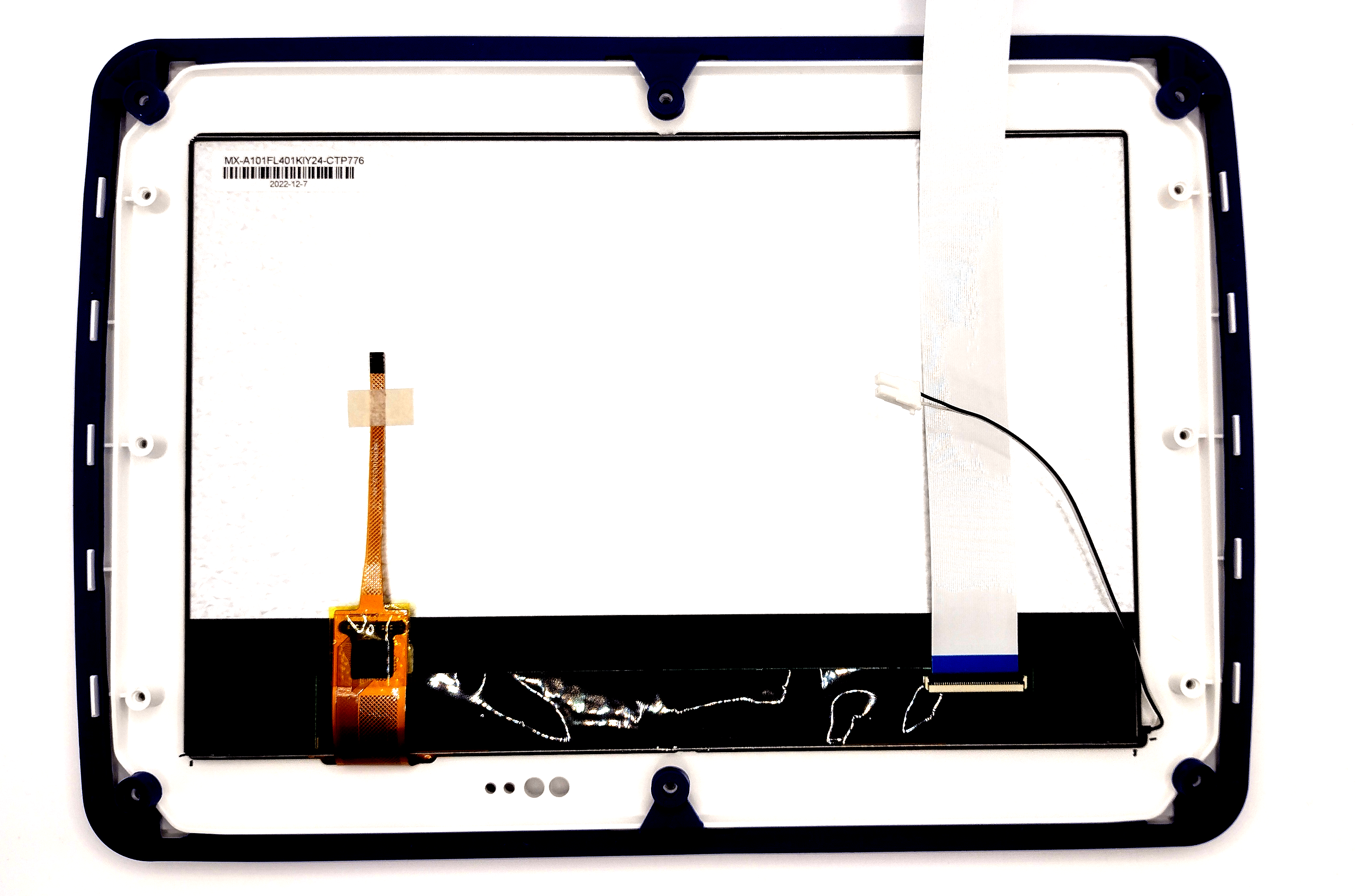
Fig.: Housing cover with 10″ display
After the display has been installed, press the display onto the housing several times with two fingers along the adhesive strips.
Finally, attach the ribbon cable to the display. The black bracket must be carefully lifted up on the open side so that the ribbon cable can be inserted. Do this with care. The bracket can be damaged quickly. The ribbon cable comes with the blue side up inserted in the center of the plug until you can feel it at the end of the slot. Then the black bracket is folded down until it snaps into place.
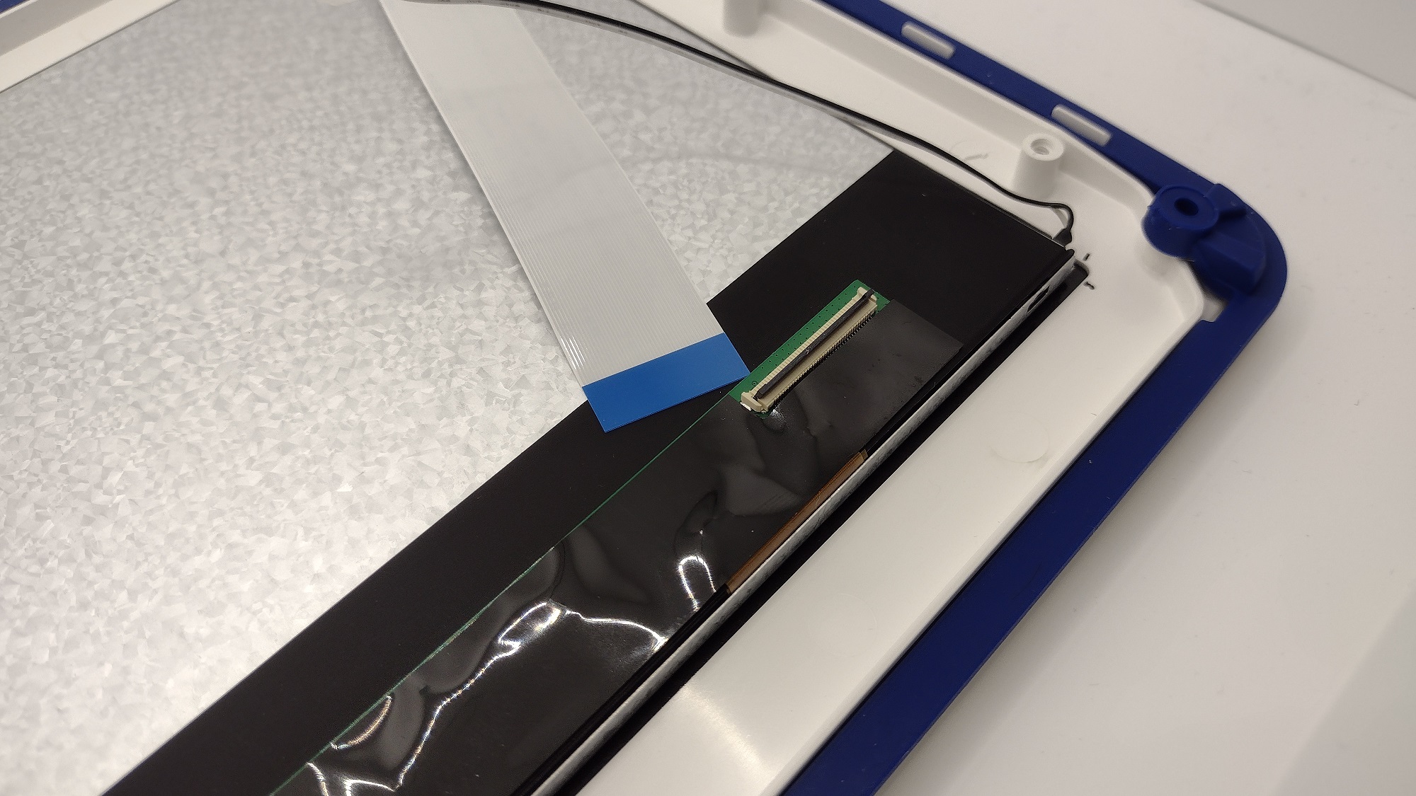
Fig.: Open mounting bracket for the ribbon cable
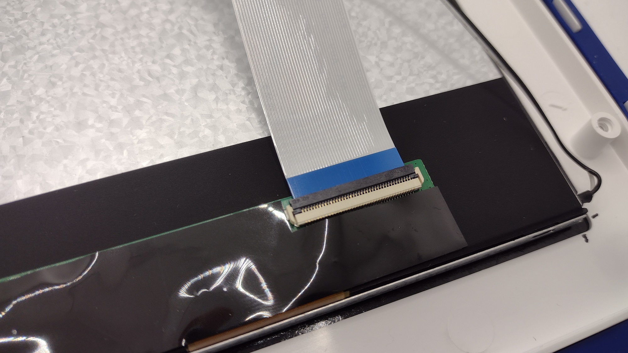
Fig.: Closed mounting bracket
Insert spacer bolts
The spacer bolts are inserted as you can see in the picture. The rear 4 spacer bolts are 16 mm long. The spacer bolts for the speakers, on the other hand, are 15 mm long. All spacer bolts are attached from below with a spring washer and screw. Do not overtighten the screws to prevent the bolts from tilting and pressing into the plastic panel.
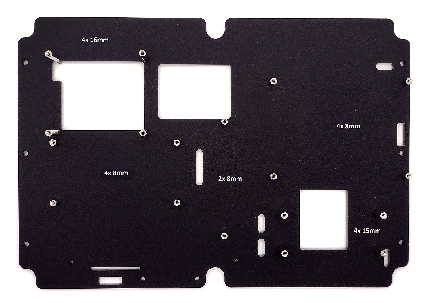
Fig.: Mounting plate with spacer bolts
Install IR receiver
The IR receiver board will be on the back of the mounting plate screwed on with two screws each with spring washers and nuts as shown in the picture.
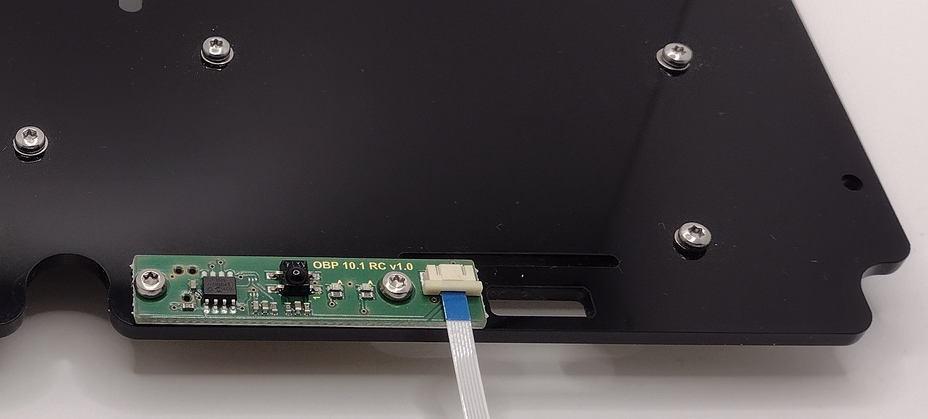
Fig.: IR receiver board
Install circuit boards
The circuit boards are installed as shown in the picture. The keyboard circuit board in the middle can also be omitted as it is not absolutely necessary.
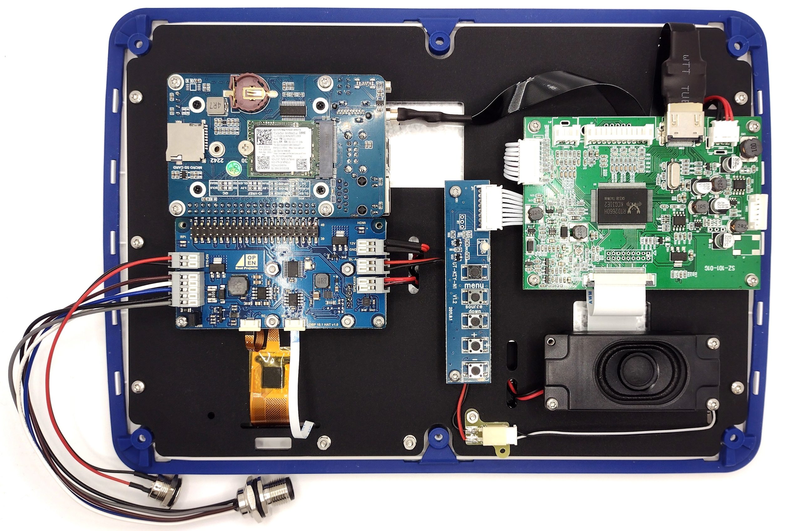
Fig.: Boards installed and wired
cabling
Some cables need to be prepared for wiring. This refers to the correct length and the stripping and tinning of the cable ends. The cables should be approximately 5…6 mm stripped and tinned be.
- speaker cable
- shorten and tin the ends
- HDMI power cable
- Unsolder the barrel connector and tin the cables in pairs
- NMEA2000 connector
- Strip and tin the ends
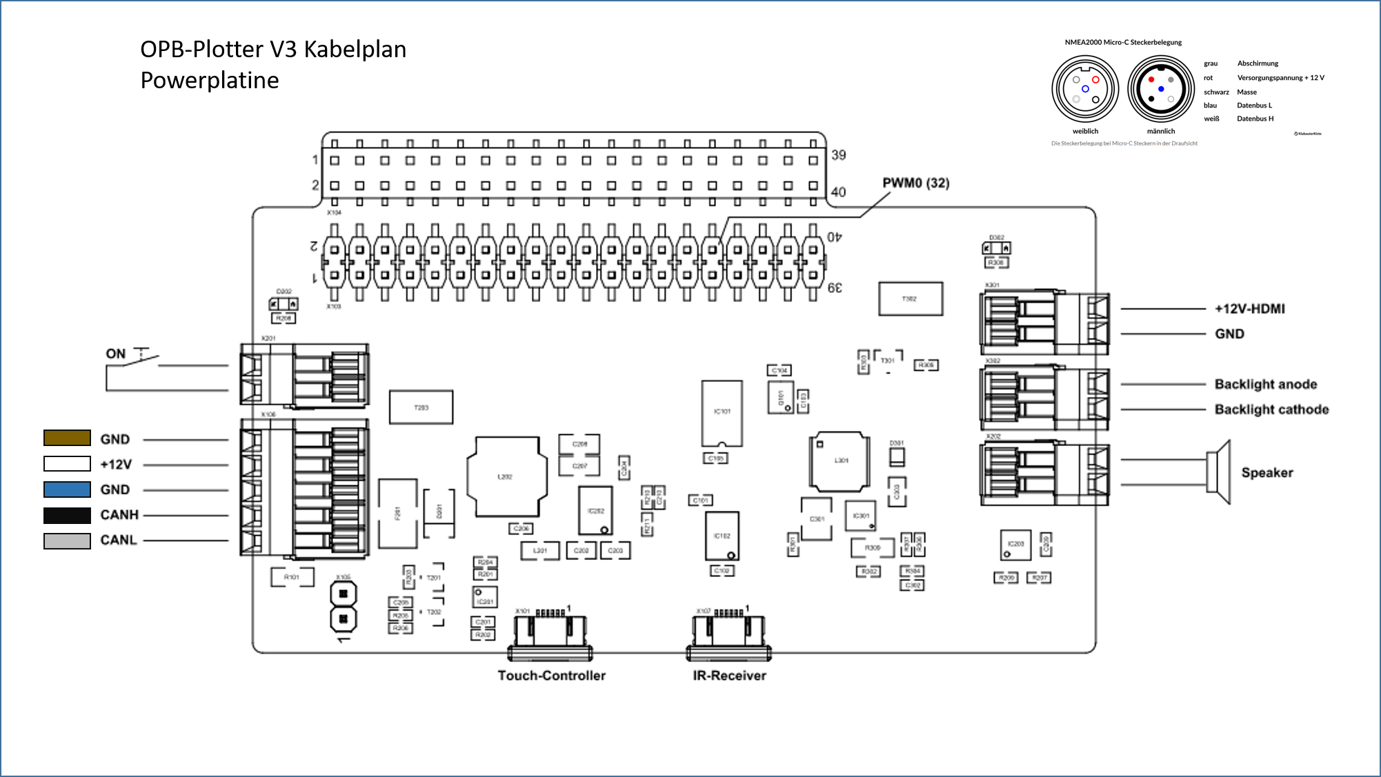
Fig.: Cable plan
The cables from the speaker and the HDMI board are very delicate. If you apply too much pressure when stripping, some stranded wires will quickly be severed and weaken the already very tight cross-section. Be careful when stripping and do not heat the stranded wire for too long when tinning or the insulation will melt and pull back. There are gray connection terminals on the Raspberry Pi HAT where you can connect the cables. The connection can be opened with a narrow screwdriver with a blade width of 3…4 mm by sliding the white slider to the outside of the circuit board. Then insert the cable until it stops and close the slider in the opposite direction by inserting the blade into the slot and moving it.

Fig.: Raspberry Pi HAT (bottom left NMEA2000 connection)
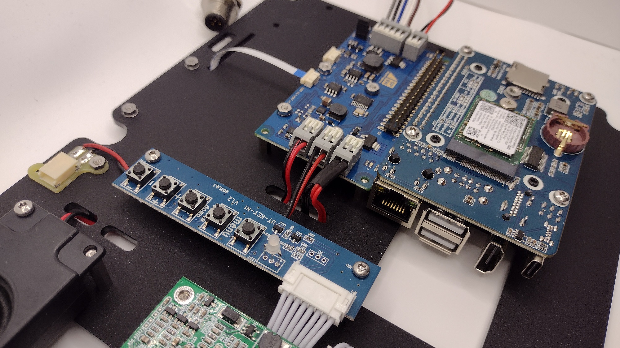
Fig.: Keyboard circuit board
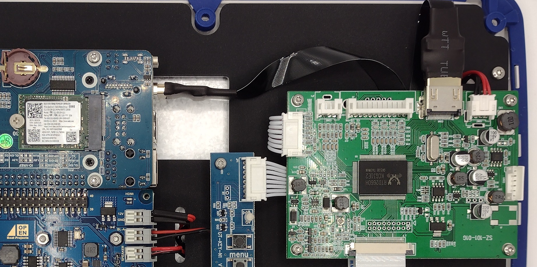
Fig.: HDMI connection between Raspi and HDMI controller
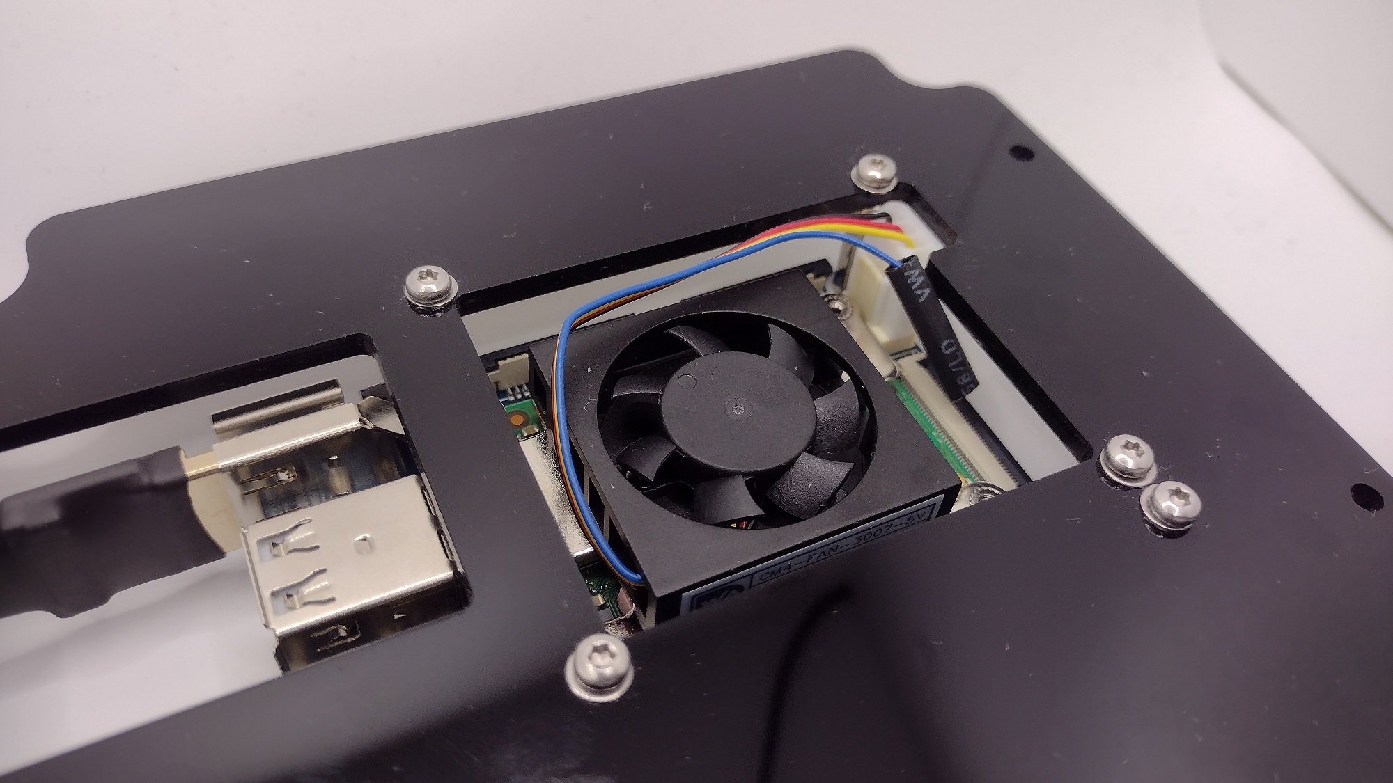
Fig.: Fan cable with removed PWM control (blue cable)
Attachment of the touch and IR board ribbon cable is slightly different than the display ribbon cable. To open the attachment, pull the outer frame forwards by approx. 1...1.5 mm. Then you can insert the ribbon cable with the black or blue side up and carefully slide the frame back in at the sides. Excess ribbon cable can be looped under the board. Be careful not to kink the ribbon cable.
Fig.: IR receiver connection cable below (touch is still missing)
The cables from the speaker, the HDMI power supply and the LED display lighting can be routed on the back of the mounting plate. With some adhesive tape, the cables can be neatly sorted and attached to the back.
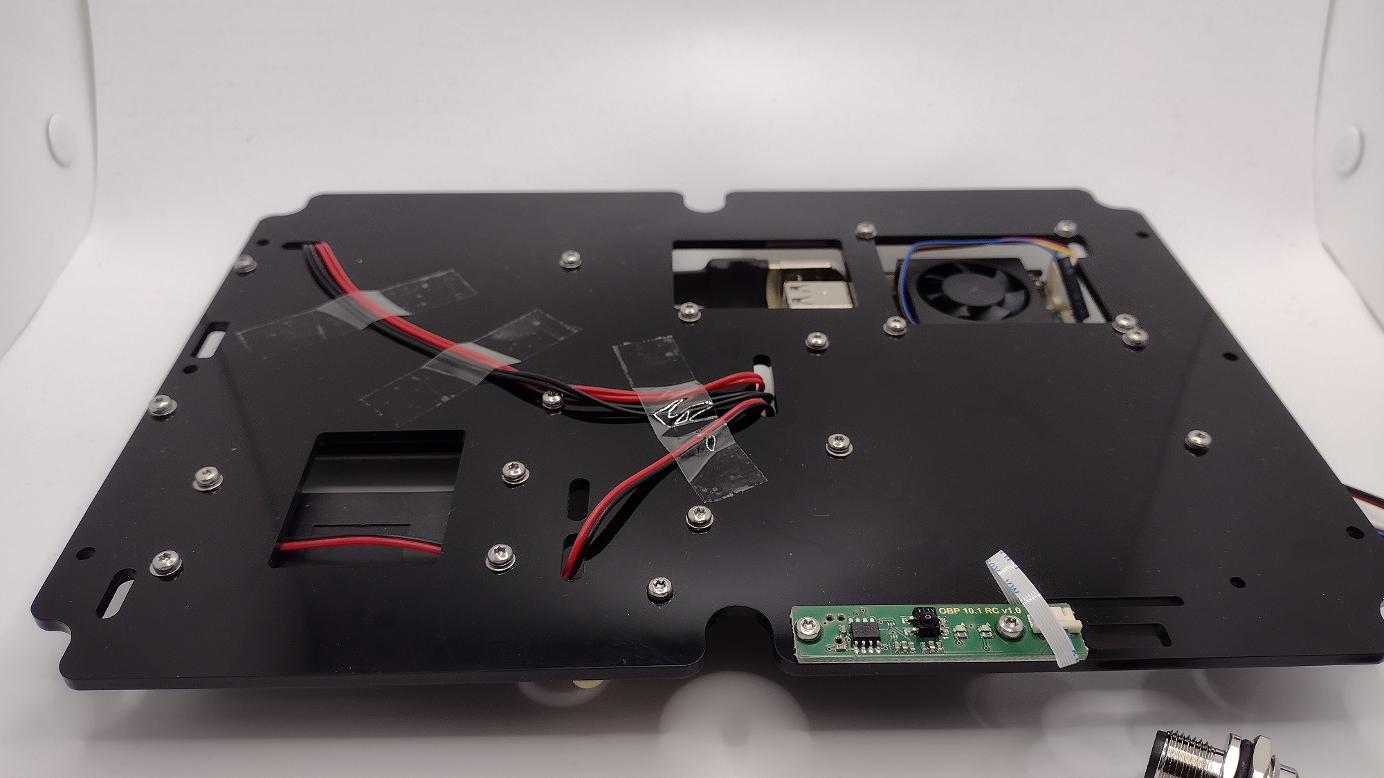
Fig.: Rear of mounting plate
system test
…
At the end, all screws are secured with screw lock lacquer or nail polish.