 |


3D view* (Click on the picture, wait for the download and move the object with the mouse)
The wind sensor Yachta is used to measure wind speed and wind direction on boats. It is installed on the mast and supplied with 12V. The data transmission of the NMEA0183 telegrams takes place wirelessly via WiFi. The wind sensor contains an access point and a small web server. A mobile phone with a web browser is used to display the measured values. The measurement data can also be displayed in other programs such as SignalK, AvNav, OpenCPN, Navionics or similar that can process NMEA0183 data.
Copyright and Licenses
The copyright and the licenses must be observed when replicating. The wind sensor can be reproduced by anyone free of charge, as long as there are no commercial intentions and money is earned with it. With commercial intentions Contact with open boat projects be included. We will then clarify what options there are for commercial, non-exclusive exploitation.
If these instructions were helpful to you, we would be delighted if you would support us with a donation. This way we can publish other interesting projects. You also help ensure that this site continues to be available to the general public free of charge.
![]()
| area | License | comment |
| documentation | CC-BY-NC-SA | All online and print documents |
| hardware | CC-BY-NC-SA | 2D, 3D CAD files |
| software | GPL V3.0 | Firmware, app |
Difficulty level and time required
| total |
||
| Level of difficulty | 4 |
|
| Time required [h] | 2…3 |
|
| Details |
||
| mechanics | 2 | |
| electronics | 6 | |
| software | 2 | |
| network technology |
4 |
The assembly instructions are aimed at those with technical skills. If you want to solder the electronics together, you should have experience in assembling SMD components. Without such experience, it is better to purchase a fully assembled board. Programming the ESP8266 microcontroller requires some experience in dealing with microcontrollers and programming adapters, but is not a major hurdle for beginners. If you want to modify the software yourself, you should be familiar with the programming language C and programming environments such as the Arduino IDE or PlatformIO. Since data is transferred via WiFi networks and TCP / IP, you should have knowledge of the configuration of WiFi routers and network technology.
Tools, aids and consumables
| Tools | use | Source of supply |
| tweezers | ||
| Cutter knife / scalpel | ||
| Allen set | ||
| Open-end wrench set | ||
| Screwdriver set | ||
| Fine pliers | ||
| Electronics side cutter | ||
| Electronics soldering iron | ||
| Desoldering pump | ||
| USB cable (mini USB) | programming | |
| USB serial adapter (3.3V) | programming | |
| Aids | ||
| Digital multimeter | Function test | |
| Laptop / pc | programming | |
| mobile | Function test with app | |
| Oscilloscope (optional) | Function test | |
| Consumables | ||
| Tin solder D 1mm | ||
| Desoldering braid (optional) | ||
| Silicone oil / fine oil | ||
| Dupli-Color Aerosol Art, clear lacquer matt | Protective varnish for plastic parts | bauhaus.de |
| 2K adhesive Weicon RK-1300 | conrad.de | |
| Alcohol 99% | Drugstore, hardware store | |
| Q tips | Drug store | |
| Rag |
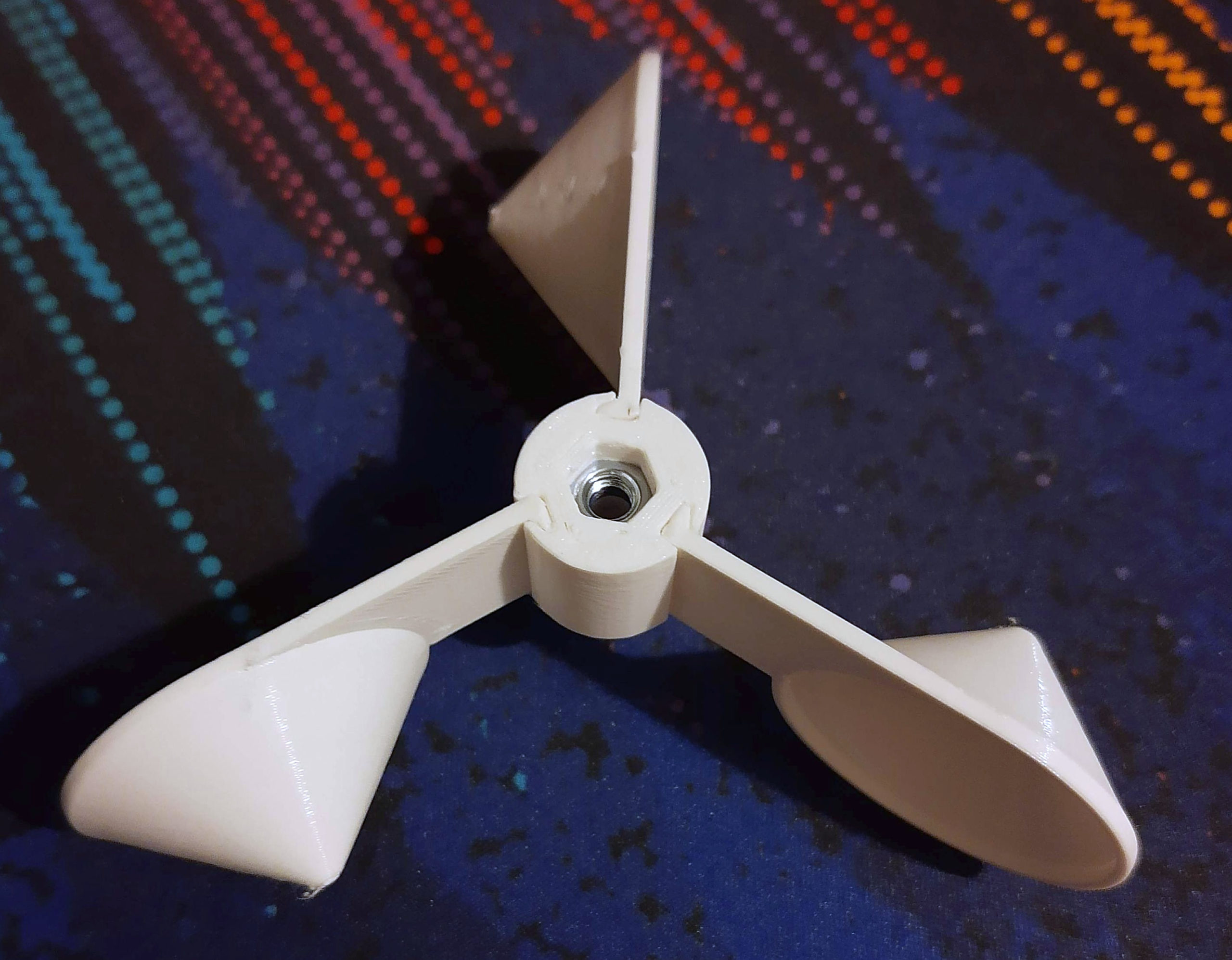
functionality
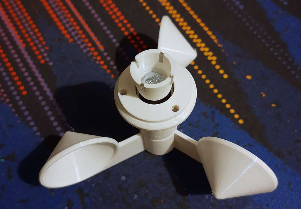
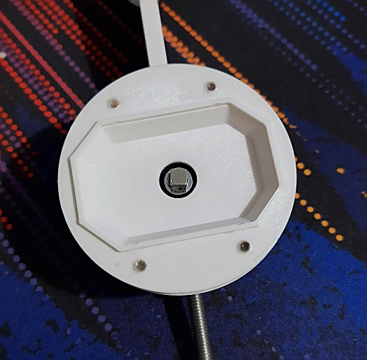
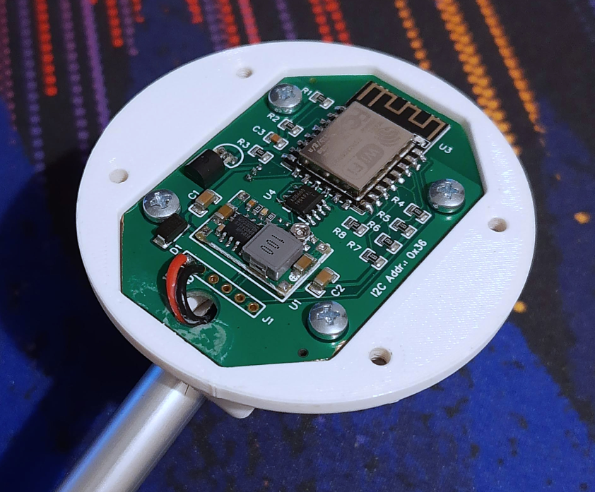
The wind sensor Yachta is an anemometer with a rotating cup wheel. The wind direction is measured using the wind vane. The wind vane aligns itself according to the wind direction. There is a neodymium magnet on the underside of the axle, whose magnetic field is measured by a non-contact magnetic field sensor (AS5600), which is located on the green circuit board in the middle. The angles are divided into 4096 partial steps per 360° and transmitted to the ESP8266 microcontroller via the I2C bus, resulting in an angular resolution of approx. 0.1°. The wind speed is measured using the shell wheel, on whose upper axis there is a ring with several small magnets. During rotation, the magnets move past a Hall sensor and trigger a digital switching signal that is evaluated by the ESP8266. The firmware of the wind sensor contains an access point and a small web server with which the measurement data can be transmitted via WiFi. With a mobile phone you can log into the WiFi network of the wind sensor and view the measurement data with a web browser. There is also an Android app with which the measurement data can be displayed. The wind sensor can also be connected to other evaluation and display software that is able to evaluate NMEA0183 data via TCP port 6666.
For mechanical details, you can explore the functional principle in the 3D view.
 |
3D view* (Click on the picture, wait for the download and move the object with the mouse)
Project documents
- Link to the sailing forum
- Project page on GitLab
- 3D CAD files
- Circuit diagram V1.2
- Interactive component list V1.2
- Gerber data for circuit board production V1.2
- Aisler PCB manufacturing V1.2
- Firmware source code, binaries
- App source code, binaries
- Operating instructions for the app
- Data sheets and other documents
- Contact options
- Sailing Foum (German and English)
- Open boat projects (German and English)
Helpful links
- Video about the wind sensor Yachta (30 min, German)
- Weicon RK-1300 product and processing instructions
- Weicon glue video
- Soldering tips
- Video for soldering
- Soldering of SMD components
- Video on using a multimeter
- Commissioning of a new circuit
Important instructions
Before you start the project, take the time to read these tips to avoid the most common mistakes. Before you get started, try to understand how the wind sensor is constructed and how it works. Use the contact options if you have any questions or are unclear. In this way you will be able to successfully implement your project.
PETG is ideal as a filament for the 3D parts. It has a higher temperature stability than PLA and can be processed just as well. Be careful not to use any dark filaments, as the wind sensor can heat up considerably when exposed to the sun and the plastic can become soft. The dimensional stability of PETG is only given up to 70°C. White filaments have been found suitable. Black PETG filaments, on the other hand, are unsuitable. If you absolutely want to build a black wind sensor, then it is best to use ABS. However, the printing is a bit more complicated than PETG and requires experience in handling ABS.
The printed parts of the wind sensor are not waterproof and must be painted afterwards. Otherwise there is a risk of water penetrating the wind sensor and damaging the electronics. Just any paint cannot be used as paint, since ordinary paint does not adhere to plastic parts. The paint listed in the component list is particularly suitable for direct plastic coating without pre-treatment. It is easy to process and achieves a good painting result. If you use alternative paints, check the suitability on test objects before you paint the wind sensor.
Note that the adhesive used must have a certain residual elasticity in order to be able to compensate for the expansion or shrinkage of different components when the temperature changes. After all, temperature changes of approx. 100 ° C (-10… 90 ° C) can occur between summer and winter and this can break adhesive bonds.
If you have little experience with SMD electronics, buy an assembled and programmed board. This saves you a lot of time and effort when troubleshooting.
If you want to program the electronics yourself, make sure you use a USB-to-serial converter with a 3.3V TTL signal level. Converters with a 5V TTL level are unsuitable and can destroy the electronics. Basically, you should be careful with the electronics and not unintentionally bring them into contact with metal parts. This can lead to short circuits and damage the electronics. Also, be careful not to be electrostatically charged. There is a particular risk in winter when the air humidity is low. Before working on the electronics, you can discharge yourself on a metallic water pipe or a heating pipe.
Schedule
The following component list refers to the assembly with a ready-equipped and possibly also programmed circuit board. If you want to assemble the circuit board yourself, you will find a parts list for the electronic components in the GitLab repository. Alternatively you can use the interactive parts list use which is ideal for manual assembly of the circuit board.
The sources of supply listed in the component list may no longer be up-to-date. Then it is best to look for alternative procurement options on the Internet.
| position | number | Component | material | Source of supply | comment |
| 3D parts | |||||
| 1 | 1 | Wind vane | PETG / ABS | fane.stl | |
| 2 | 1 | Substructure wind vane | PETG / ABS | fane_support_small.stl | |
| 3 | 1 | Upper part 1 | PETG / ABS | top_1.stl | |
| 4 | 1 | Upper part 2 | PETG / ABS | top_2.stl | |
| 5 | 1 | Lower part | PETG / ABS | bot.stl | |
| 6 | 1 | Lower part for ball bearings | PETG / ABS | bot_ball_bearing.stl | |
| 7 | 1 | Magnet holder | PETG / ABS | magnet_holder_2.stl | |
| 8 | 3 | Peel | PETG / ABS | cup_round.stl | |
| 9 | 1 | Bowl base | PETG / ABS | base_cup_wheel.stl | |
| 10 | 1 | Base | PETG / ABS | base_power.stl | Mounting foot |
| Purchased parts | |||||
| 11 | 1 | Yachta board equipped | FR4 | Contact form OPB, Aisler (unpopulated board) | Open Boat Projects, Aisler board manufacturer |
| 12 | 4 | Magnet D3x4 mm | Neodymium | supermagnete.de | windmill |
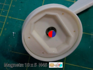
| 13 | 1 | Magnet 5 x 5 x 5 mm | Neodymium | supermagnete.de | Wind direction |
| 14 | 2 | Ball bearing 625 (16 x 5 x 5 mm) | V2A, ABEC9 | kugellager-express.de | Upper and middle ball bearing |
| 15 | 1 | Ball bearing 695 (13 x 5 x 4 mm) | V2A | kugellager-express.de | Lower ball bearing |
| 16 | 3 | M5 washer | V2A | bauhaus.de | |
| 17 | 1 | M5 nut | V2A | bauhaus.de | |
| 18 | 2 | M5 stop nut | V2A | bauhaus.de | |
| 19 | 1 | M5 x 25 countersunk head screw | V2A | bauhaus.de | Wave for wind vane |
| 20 | 1 | M5 x 60 Phillips screw | V2A | bauhaus.de | Shaft for cup wheel |
| 21 | 1 | M6 x 60 Allen screw with shaft | V2A | bauhaus.de | Pointer for wind vane |
| 22 | 11 | M3 x 10 Allen screw | V2A | bauhaus.de | for housing parts |
| 23 | 1 | D10 x 1 x 300 aluminum tube | aluminum | bauhaus.de | Holding rod |
| Software / firmware | |||||
| 24 | 1 | Firmware V1.20 | Binary | GitHub | for ESP8266 |
| 25 | 1 | Android app | APK | GitHub | Android 5… 11 (3, 4 limited graphics display) |
Mechanical assembly
For mechanical assembly there is one in the GitLab repository picture gallery as a zip file that you can download. The pictures are quite helpful and show in detail how to proceed. Below is an X-ray of how the internal parts are installed.
![]()
Fig: Arrangement of the inner parts in the wind sensor Yachta
If you want a more detailed view, you can go to Online CAD program Onshape Register for free and search for "Yachta" in the public repository. The entire project can be copied to your own workspace and viewed from all angles. Components can be clicked on, and right-clicking makes them transparent. Anyone who wants to customize the wind sensor can do so in Onshape. STL export allows you to export files that a slicer can prepare for a 3D printer.
Painting
PETG is a plastic that cannot be painted directly due to its surface properties. The substrate must be specially pre-treated. However, there are special paints that can be applied directly to PETG without a primer or pre-treatment. Dupli-Color's recommended Aerosol Art Clear Varnish (matt or gloss) is a polymer varnish containing acetone and n-butyl acetate in a 400ml aerosol can. It can be applied directly to PETG in multiple layers with no drying time.
The painting can be done in two ways. Either by painting with a brush or by spray can. In principle, 3 layers should be applied with each method. Appropriately thinner should be applied to the fits. In principle, the layer structure should be thin and not have any running noses. Run noses are to be removed when wet.
If possible, spray painting should be done outdoors, as more paint is sprayed on the side than on the component. A piece of cardboard should be placed in the background to absorb the excess paint. Depending on the paint manufacturer's recommendation, a minimum distance of 30 cm from the component should be maintained when painting. Otherwise you wear too much paint and it comes to runs. the Parts are slowly rotated continuously while spraying or moved, so that all areas can be reached. Painting the inside of the shell is a bit more difficult because you can't really see how much paint has been applied. You should be more cautious here, as you tend to apply too much. The correct layer thickness is reached when the wet paint starts to shine.
The paint is touch-dry after a short time and finally dry after 24 hours.
Cup wheel
The shells can best be slid into the base from below. To get it all the way in, it may be necessary to use a hammer for the last millimeters. You just have to be careful not to break the shells.
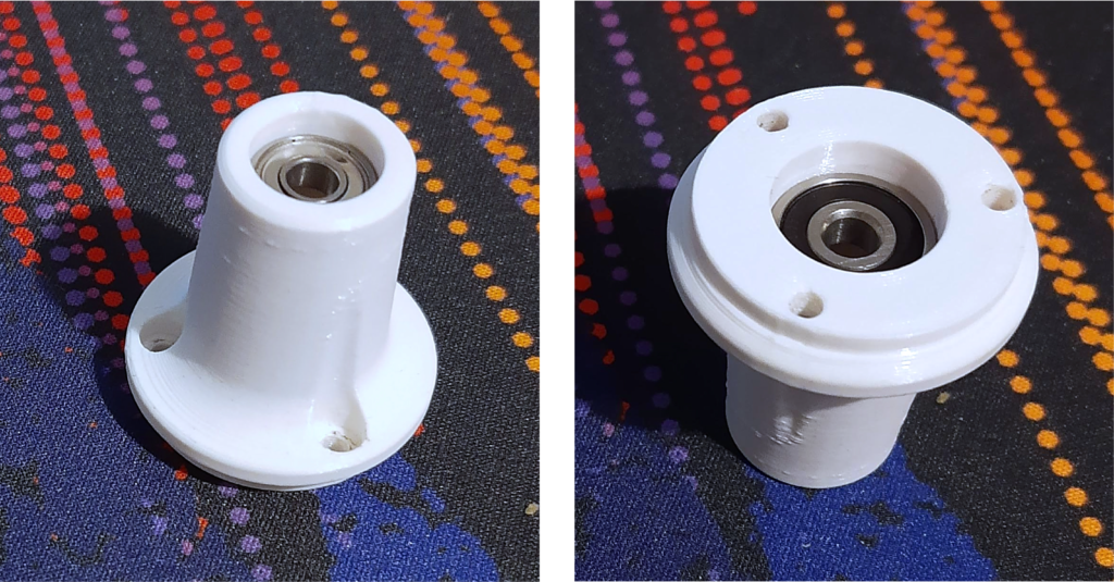
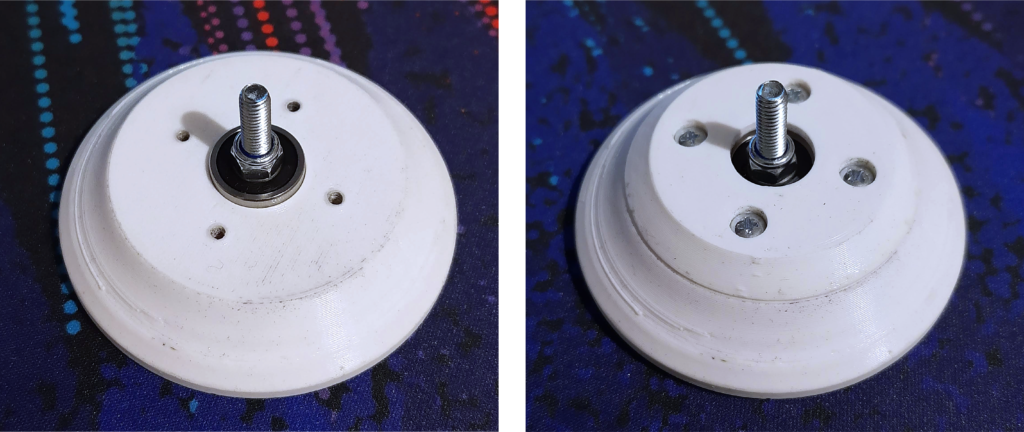
Magnet holder and lower bearing
The 695 ball bearing is inserted from below and the 625 ball bearing from above up to the respective edge in the lower part of the wind sensor.
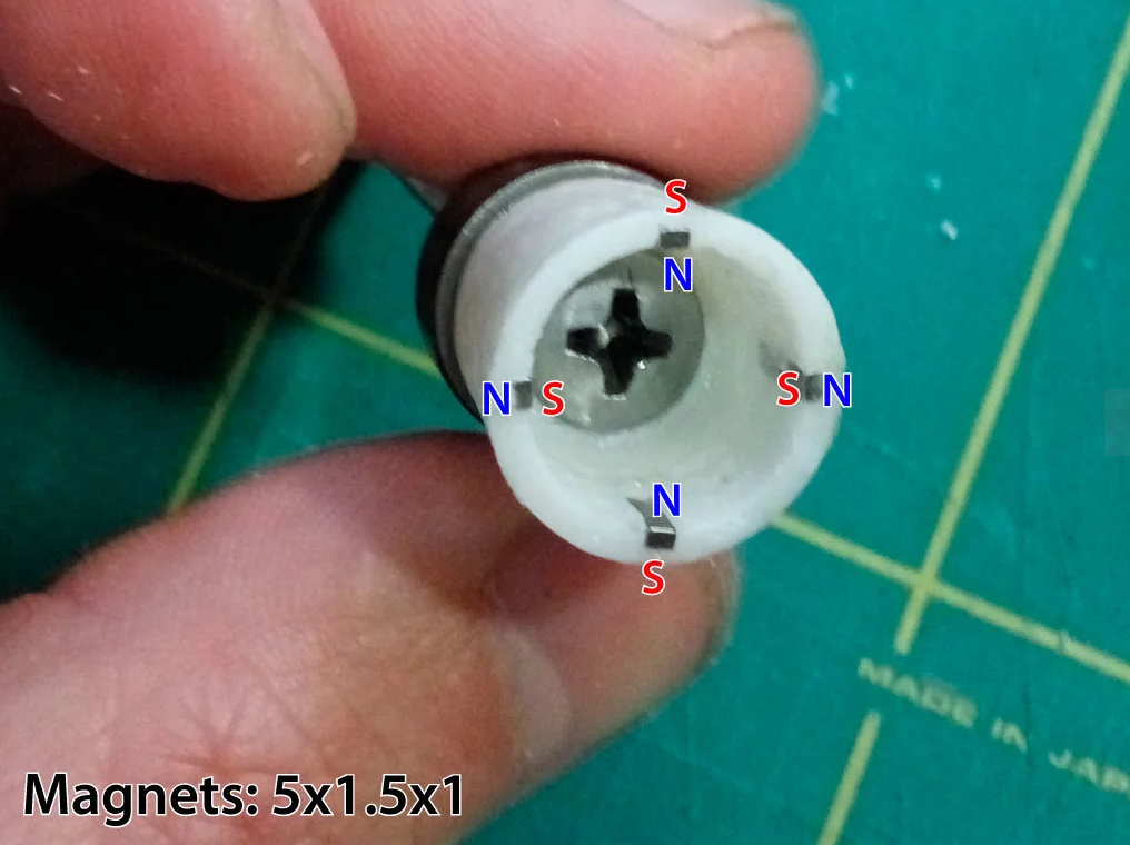
The magnets can be glued relatively easily in the magnet holder with superglue. When installing the magnets, ensure that the polarity is correct.
To simplify assembly, you can temporarily stick adhesive tape on the inside of the magnet holder and then press the magnets into the recesses from the outside. The adhesive tape can be removed again as soon as the superglue has dried. The M5 x 60 mm screw can then be fed through the magnet holder and secured from below with a nut. The holder can then be inserted through the lower part.
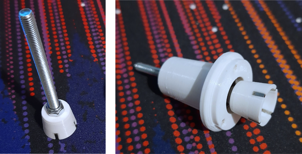
In the last step, only the shell wheel has to be screwed on. Here you should be careful not to screw the whole thing too tight, so that the bowl wheel can turn easily. When the desired ease of movement is achieved, the screw on the lower nut can be secured with Loctite.
Wind vane and substructure
The substructure of the wind vane consists of an upper and a lower part. The 625 ball bearing is inserted into the top of the lower part, the M5 x 25 countersunk screw is inserted from below and secured with a nut. At this point, too, make sure that the clamped screw can turn easily. The upper part is then screwed onto the lower part with four M3 x 10 screws to hold the ball bearing in place.
In the next step, an M5 nut is inserted into the recess of the wind vane and can also be fixed there with glue.
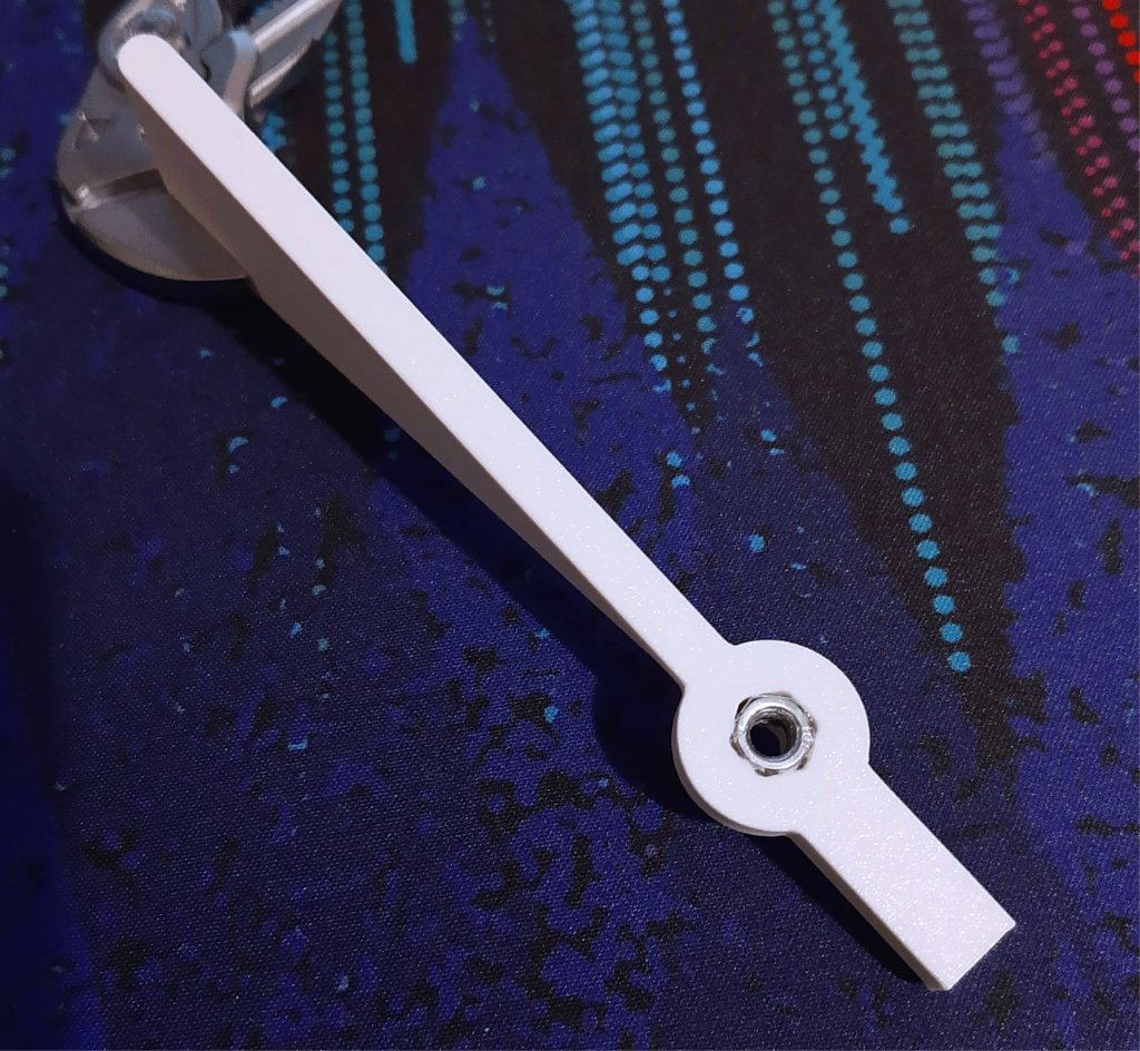
The base of the wind vane can now be placed on the substructure that has already been installed and then fixed with the wind vane.
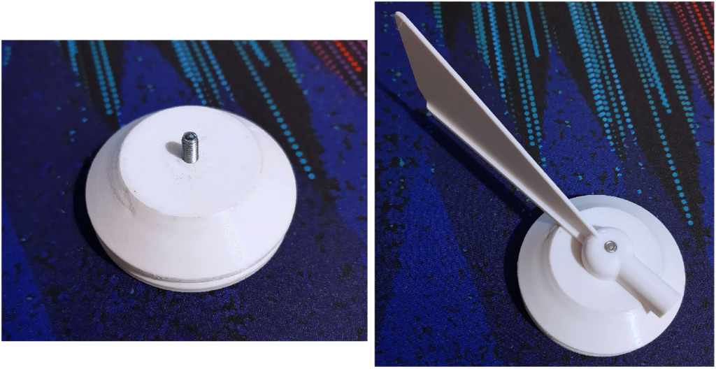
Finally, the 5 x 5 x 5 mm magnet must be glued to the countersunk screw. It is also important to ensure that the magnet is correctly aligned. The outer edges of the magnet should be aligned parallel to the wind vane. If there is still an alignment error, it can be corrected using a Offset under Device Settings Getting corrected.
Standpipe and base
The aluminum tube slides into the base of the sensor and can then be holed in place for the cables. Then the circuit board with the already soldered cables for the power supply can be inserted into the recess provided. To do this, the cables must first be routed into the aluminum tube. If everything is in the right place, the circuit board can be attached with four M3x10 screws.
software
The software was programmed in C with the Arduino IDE. Compiling the firmware yourself requires experience in using the Arduino IDE and installing the required software libraries in the correct version. Due to the high complexity, the firmware has already been compiled and made available to the user as a binary file. This saves you the hassle of compiling the firmware yourself.
Firmware installation
The firmware can be installed on the ESP12-E before soldering in using a programming adapter or on the fully equipped circuit board.
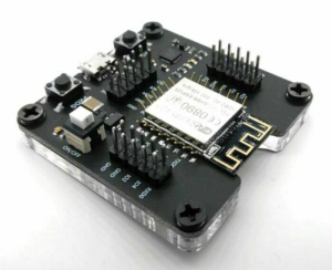
Fig: ESP8266 programming adapter for external programming
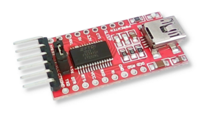
Fig: Programming adapter for programming on the circuit board
When using a programming adapter for programming on the circuit board, make sure that the signal levels for TX and RX support 3.3V TTL levels. 5.0V TTL levels cannot be used as this can damage the ESP12-E. The programming adapter is to be connected as shown in the picture. You have to make sure that RX is connected to TX and TX to RX. Otherwise you will not be able to carry out any other program transfer.
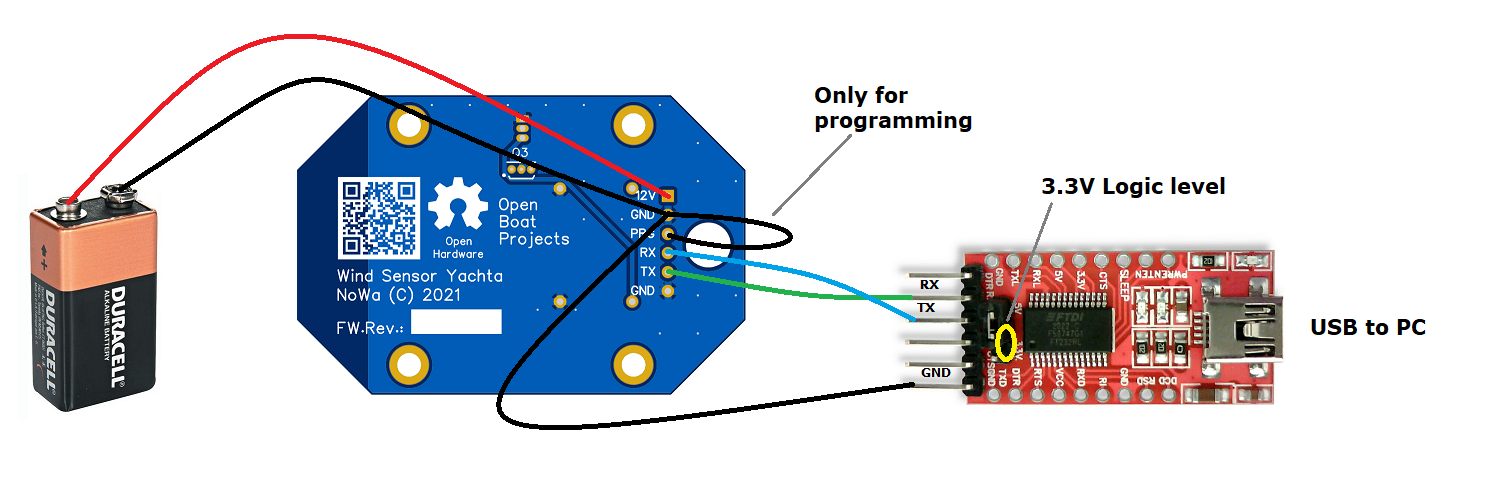
Fig: programming circuit
Programming instructions
- Build the programming circuit together
- Connect PRG and GND
- Connect the USB programming adapter to the laptop or PC
- Connect the 9V battery block
- Programming software NodeMCU Flasher start on laptop or PC and load firmware
- Start the programming process
- If programming is successful, disconnect USB and switch off 9V
- Separate PRG and GND
- Disconnect the programming circuit from the circuit board
- Switch on 12V and check firmware via WiFi connection
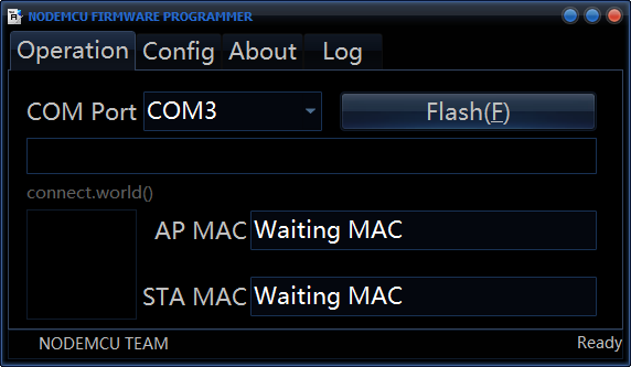
NodeMCU Flasher
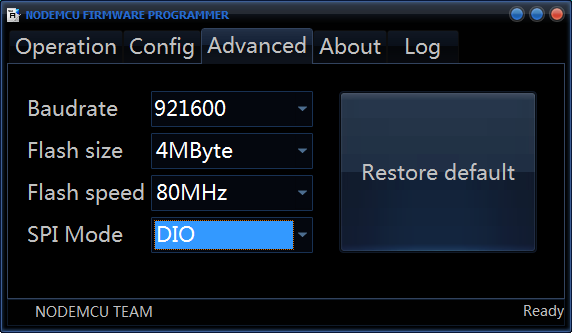
The easy-to-use Windows tool NodeMCU Flasher be used. The EXE file can be started directly without any special installation. The tool can be used for both external and in-circuit programming. The first thing to do is take Advanced made the following settings.
After that, under Config the Current firmware file firmware_Vx.xx.wsb selected.
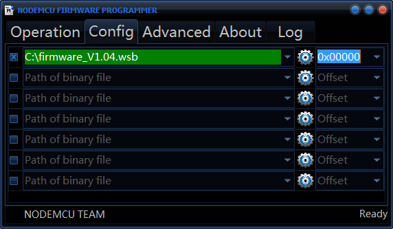
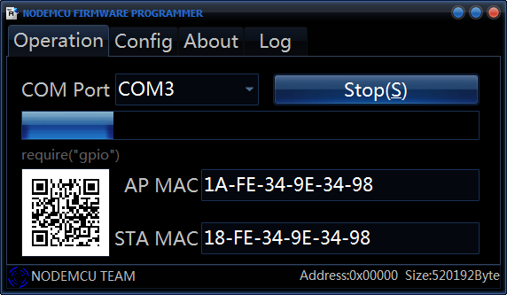
You open up to flash surgery and selects the corresponding interface to which the adapter is connected. Then you press Flash and wait until the firmware is loaded.
The progress of the transfer is displayed during the flashing.
If the firmware has been successfully loaded, the following screen will appear.
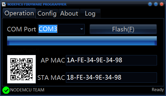
After the transfer, the programming tool can be closed and the adapter removed.
To start the new firmware, the wind sensor needs to be rebooted. After the reboot, the wind sensor creates a WiFi network called Yachta , which you can log in to 30 seconds after the restart using a mobile phone and the password 12345678. The blue LED will then turn off 3 times briefly when the web server is ready. If you then access the wind sensor's website with the Android app (http://192.168.5.1), you should see the following. If access data from an access point is entered under WLAN Client SSID and WLAN Client Password, the wind sensor logs into this WiFi network. The blue LED will then turn off to indicate a successful connection. If measurement data is retrieved via port 6666 from a program such as OpenCPN or similar, the blue LED always flashes briefly when a telegram is transmitted.
The last thing that needs to be done in the firmware is the correct type of wind sensor Yachta must be selected in the configuration so that the data is displayed correctly.
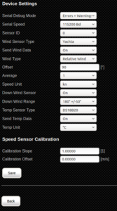
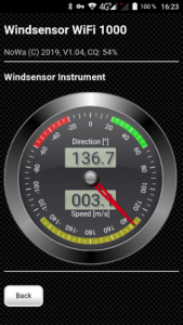
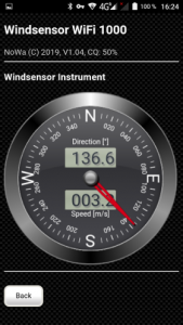
Fig: Device Settings for Yachta
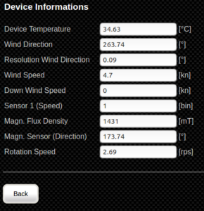
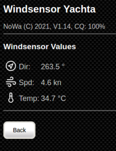
Fig: Measured values for Yachta
Function test
The function test is limited to checking whether the sensors are giving off correct signals. The instrument view is best suited for this. More detailed information on the wind sensor is available below device info to find.
Troubleshooting
What is the meaning of the flashing code of the blue LED?
The blue LED indicates the status of the WiFi connection.
| LED state | meaning |
| permanently off | Connected to external WiFi |
| permanently on | No external WiFi connected |
| flashes briefly | Data is transmitted via external WiFi |
| permanently on briefly interrupted | Data is transmitted via internal WiFi (NoWa) |
Basically, a distinction is made as to whether data is transmitted via an external WiFi or via the internal WiFi (NoWa). Internal WiFi means that you have connected to the WiFi provided by the wind sensor itself. With an external WiFi, the wind sensor connects to another WiFi network as a client.
As long as the shell wheel is rotating, wind data is transmitted once per second. If the ring gear does not rotate, the data rate is reduced. A telegram is then only sent every 3 seconds.
The wind direction display is incorrect
Depending on how the 5x5x5 mm magnet for the wind direction display is glued in, there may be a deviation in the display instrument. That's not too bad, because about a Offset under Device Settings the error can be corrected.
The true wind readings are incorrect
The wind sensor Yachta can only display the relative wind, as there are no reference values for the orientation of the boat in the wind sensor. The true wind can only be displayed correctly if the wind sensor is installed as a stationary weather station on land with the correct north orientation. On a moving boat, only relative wind or apparent wind can be displayed.
The wind direction indicator does not respond
- Is the magnet installed the right way round? (correct north-south orientation)
- Is the field strength of the magnet strong enough? (Magn. Flux Density must be greater than 1000 mT)
- Is the distance between the magnet and the chip small enough? (approx. 1 mm distance)
- Is the right one Wind sensor type under Device Settings selected? (Yachta)
The wind speed display does not work properly
- Is the Hall sensor close enough to the magnetic ring? (approx. 1 mm distance)
- Are the magnets installed the right way round? (correct north-south orientation)
- Does the axle have too much play? (The magnetic rim must not swing back and forth and change the distance to the Hall sensor)
The wind speed display shows twice the speed
The problem is often caused by incorrect alignment of the magnets in the magnetic ring. The magnets must have alternating polarity. If all magnets are aligned in the same way, 4 impulses are recognized instead of 2 impulses. The speed is therefore too high by a factor of 2. It is easiest if you stick the magnets together before installation and remove them individually and mark one of the sides that are sticking, eg always the left side. This makes it very easy to check the alignment of the magnetic field during installation. With a hand compass this would also be possible, albeit a bit more difficult.
The Android app cannot be installed on Android 11
As of Android 11, the security settings have been tightened and apps (apk files) can no longer be installed from external sources. This is to prevent programs from being installed unintentionally via Internet sites. Every time an apk file is downloaded, its file extension is automatically renamed and the file can no longer be started for installation. Subsequent renaming of the file in apk under Android is not possible. In order to be able to install the app on Android 11 anyway, a small detour via the file transfer function has to be made. To do this, the apk file is downloaded to a PC and transferred to the mobile phone's download folder using a USB cable. The apk file can then be installed with the internal data manager of Android 11.
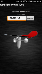
It is not possible to connect to the wind sensor via WiFi
After the wind sensor is supplied with 12V, the WiFi network of the wind sensor opens after 30s with the name NoWa. The password is 12345678. Some mobile phones and tablets cannot correctly deal with the wind sensor's AsseccPoint not having an internet connection. Whenever you see the website http://192.168.5.1 wants to call up, the request is routed to the Internet instead of to the wind sensor. The routing in the mobile phone or tablet is incorrect. The same problem occurs with the Android app as well. To fix the error, you can disconnect the mobile phone's mobile connection to the Internet. Then the wind sensor Yachta is found again.
If AVnav or OpenPlotter is used on a Raspi and the Raspi also provides the access point to which the wind sensor is to be connected, it takes a certain amount of time after switching on the supply voltage until the Linux operating system has started up and the access point is ready. The boot phase can last 2…3 minutes. If the supply voltage of the wind sensor is switched on at the same time, the wind sensor tries to log into the external WiFi network of the Raspi for 30s. However, since the Raspi needs much more time to boot than the wind sensor, the WiFi connection fails. The connection timeout can be set from 30s to 2 min or more under Device Settings. The wind sensor then waits correspondingly longer until the connection timeout occurs. The WiFi connection can be checked with the blue LED on the circuit board. If the LED is off, the wind sensor has logged into an external WiFi network as a client. When data is being transferred, the blue LED flashes briefly.
The display of the data from the wind sensor is very sluggish
If the shell wheel does not turn, the transmission interval of the data telegrams is increased from 1s to 3s in order not to send too much data unnecessarily, because when there is no wind it does not make much sense to send the same data continuously. If the wind sensor is tested at home without wind, it can take up to 3s for wind speed data to come when you turn the shell wheel. The demo mode is very well suited for tests at home, in which constantly simulated data for wind direction and wind speed are generated. The settings can be found under Device Settings on the server mode be made.
I don't see any temperature readings
if under wind values no temperature value is displayed, then it is probably the Temp sensor type under Device Settings not properly selected. The value must be up DS18B20 stand. Temperature sensors other than the DS18B20 are not supported by the wind sensor Yachta.
I don't see any readings for humidity and barometric pressure
The temp sensor type BME280 cannot be used with the wind sensor Yachta because it is not installed on the circuit board. Humidity and air pressure cannot be displayed.
I found another error, what can I do?
If you have discovered an error, you are welcome to inform us using the contact form on the website. If possible, describe the error in such a way that it can be reproduced. We forward the error report to the respective project owner and ask them to correct it. But you can also have one yourself Bug report as issue at GitLab submit on the project page. GitLab then automatically informs the project owner.
I didn't find a solution to my problem here
If you haven't found a solution to your problem here, you can look it up at GitLab under Issues known unresolved issues check. Also look below Closed Issues to. Some solutions to errors that have occurred are also described there. If you want, you can also get help from other sailors in German german sailing forum to fetch. There are many interested people who have already successfully assembled a wind sensor Yachta and can help you. You can communicate there in German or English.
Technical specifications
| description | Value / range of values | comment |
| Measurement data | ||
| Wind speed | 0 ... 40 m / s, 0 ... 78 kn | |
| Start speed | 1 m / s | |
| Wind direction | 0… 360 ° | |
| Wind direction resolution | 0.1 ° | |
| Function type | magnetic | |
| calibration | Slope, offset | |
| Environmental conditions | ||
| Ambient temperature | 0 ... 60 ° C | |
| Storage temperature | -10 ... 80 ° C | |
| humidity | 0…100 % | |
| Weight class | IP63, IPX3 | protected against spray water |
| Power supply | ||
| Supply voltage | 7…25V | reverse polarity protected |
| Power consumption | 0.4W | typical |
| Data transfer | ||
| Network type | WiFi 11 bgn | 2.4 GHz |
| Data rate | 3 Mbit / s | |
| Range | approx. 50 m | in the free field |
| AccessPoint | Yes | max. 3 clients |
| Web server | yes, port 80 | Operating pages |
| JSON data server | yes, port 80 | Control data |
| TCP data server | yes, port 6666 | NMEA0183 data stream |
| Serial interface | yes, 3.3V level | NMEA0183, debug data, parameterizable |
| mDNS | Yes | can be switched off |
| NMEA0183 Sentences | ||
| MWV | Wind data | |
| VWR | Wind data | |
| VPW | Performance data | |
| INF | Custom code | |
| Supported software | ||
| Linux | AvNav, OpenPlotter, OpenCPN | |
| Android | Wind sensor app, AVnav, OpenCPN, Navionics, WinGPS pro | |
| Windows | WinGPS | |
| iOS | NMEAremote, Navionics | |
| Dimensions | ||
| Dimensions | 175 x 120 x 150 mm | without pipe and foot |
| weight | 150 g | with pipe and foot |
| materials | ||
| plastic | PETG: housing parts | painted |
| Metals | Alu: holding tube | anodized |
| V2A: tip, screws, nuts | ||
| miscellaneous | ||
| CE | no | |
| UL | no | |
| guarantee | no | |
| Licenses | CC-BY-NC-SA | Hardware, documentation |
| GPL 3.0 | software |
Opinions and tips
We hope that these instructions were of help to you in successfully implementing the project. Your opinions and tips are important to us. Please let us know if you got along with the instructions, had difficulties or have any tips on where we should improve the documentation. It is best to use our contact form. In this way we can enable a high quality of the replication instructions and a successful project implementation.
Hints
* Requires a 3D graphics card WebGL supports