First of all, a few important notes that you should definitely pay attention to.
Disclaimer: The descriptions of the wiring and the pin assignments correspond to what I found in my boat. Therefore, if you want to recreate the interface, you have to make sure that the wiring and pin assignments on your own boat are identical or adapt the interface accordingly. The entire description of this solution is in an experimental state and comes without any guarantee. Changes to the cabling of the boat or the electrical and electronic conditions can lead to damage or critical situations. You do so at your own risk.
General
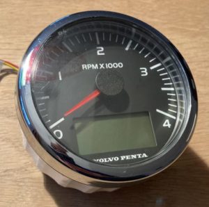
The basic installation of a Volvo Penta engine (engines D1 and D2) with EVC consists of various sensors on the engine that are connected to the EVC / MDI (electronic vessel control / motor data interface) are connected. These data are sent from the MDI to the speed instrument via a CAN bus. Often there is only the tachometer with a small LCD display to show data. However, additional instruments can be purchased and connected behind the rev counter via the so-called Easy-Link.
The speed is displayed continuously. Other values, such as cooling water temperature and charging voltage, are only alerted in the event of an error, but are not displayed continuously. The interface described here connects the engine's CAN bus with an NMEA2000 bus. The information in the VP-CAN bus, which is available as J1939 datagams, is read, evaluated and written to the NMEA2000 bus as NMEA2000 datagrams. The data implemented so far are
- Engine speed
- Charging voltage
- Cooling water temperature
- Engine hours
In the NMEA2000 bus, the information can be displayed, for example by a plotter, and provided with warning levels.
When my boat was transferred over the Unterems in the direction of DEK, that saved me from very big problems. Due to the large amount of sediments in the Ems, the outer cooling circuit was increasingly clogged. Via my plotter (MFD) I was able to notice the temperature rise early on and react accordingly. Without the interface and the display in the MFD, the alarm would have come at some point, and then I would hardly have had any options for action, that there would have been no opportunities to moor or anchor. I should have continued driving with the risk of the machine overheating.
Components
The Volvo Penta - N2K Interface consists of hardware and software components.
hardware
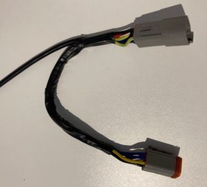
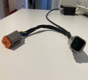
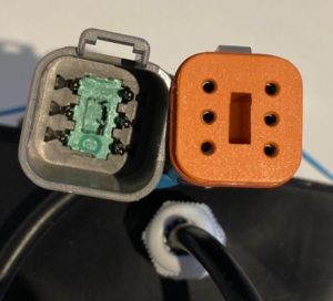
To physically connect the interface to the engine's VP-CAN bus, an adapter cable with a Y-branch is required. The cable connection from the MDI to the tachometer is made up of 6-pin 'Deutsch connectors', male and female. (e.g. https://www.kabelschuhe-shop.de/KALI-1206-DEUTSCH-DT-Steckverbinder-Set-6-polig). You connect the six pins of the plug with those of the socket. In addition, one derives 12v +, GND Can high and CAN low.
In order to physically connect the interface to the N2K bus (either Seatalk NG or NMEA2000), you also need a suitable cable. My interface is connected to a Raymarine Seatalk NG network. So I cut through a STNG standard spur cable to get a cable with a plug and an open end.
CAN bus transceiver
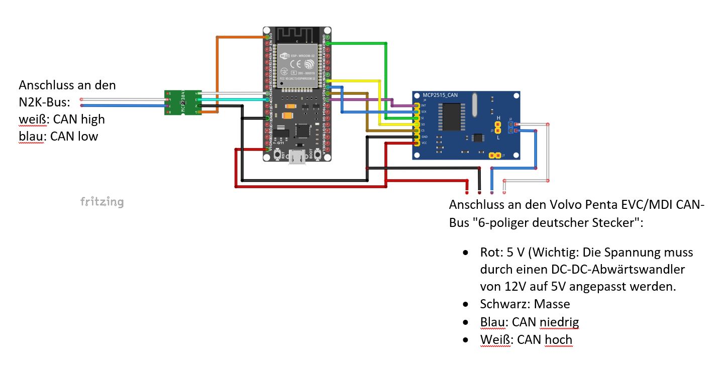
I use an SPI-MCP2515-CAN-Transceiver-TJA1050 to connect the interface to the engine's CAN bus at protocol level. This transceiver is controlled by the MCP_CAN_lib from Cory J. Fowler.
To connect the interface to the N2K bus at the protocol level, I use a Waveshare SN65HVD230. This transceiver is controlled by Timo Lappalainen's NMEA2000 library.
Since the ESP32 requires a voltage supply of 5V and the CAN bus is supplied with 12V, you also need a stepdown converter to 5V.
software
The code is available here: https://github.com/buhhe/VolvoPenta-N2K_Interface
It is based on code from:
– Timo Lappalainen https://github.com/ttlappalainen
– Andreas Koritnik https://github.com/AK-Homberger
– Cory J. Fowler https://github.com/coryjfowler
These libraries are required:
https://github.com/coryjfowler/MCP_CAN_lib
https://github.com/ttlappalainen
Volvo Penta - N2K Interface: How to proceed
- Obtain the hardware components
- ESP32 development module
- MCP2515 CAN transceiver
- SN65HVD230 CAN transmitter / receiver
- DC-DC step-down converter 5V
- A pair of 6-pin “Deutsch connectors” (male/female)
- Create the Y-branch cable. (See page 3)
- Carry out the wiring. (See page 4)
- Obtain the required libraries.
- Compile and flash the software.
- Install everything on your boat.
- Have fun!
Connection of the interface to the VP CAN bus
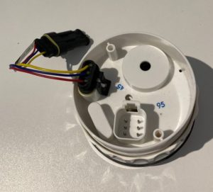
The tachometer with integrated LCD display is connected to the engine's MDI via a cable harness and a 6-pin Deutsch connector. The connection is called “Multi-Link” at Volvo Penta. The data are provided as CAN-based J1939 datagrams.
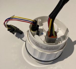
A Y-branching cable is required for connection to the bus. The cable is connected between the connector of the cable harness and the speedometer.
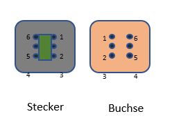
Pin assignment:
- 1 not used
- 2 CAN low
- 3 not used
- 4 minus
- 5 CAN high
- Plus, 5V
cabling
Discussion area: https://www.segeln-forum.de