First of all, a few important notes that you should definitely pay attention to.
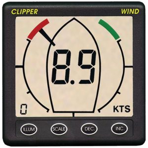
Fig .: Clipper wind instrument (Clipper)
Some older models of the Clipper wind instruments have a 5-pin DIN socket on the back for a daughter display. The wind data are also output as NMEA0183 via this DIN socket. Unfortunately, the signals do not correspond to the RS422 standard and cannot be used meaningfully any longer. The output signal used is 5V TTL levels with a very low current carrying capacity. These signals cannot be processed directly by RS422. With a small circuit as a level adapter, a differential signal according to the RS422 standard can be generated from the unipolar 5V TTL transmission signal.

Fig .: RS422 converter for Clipper Wind V1.0 with DIN sockets
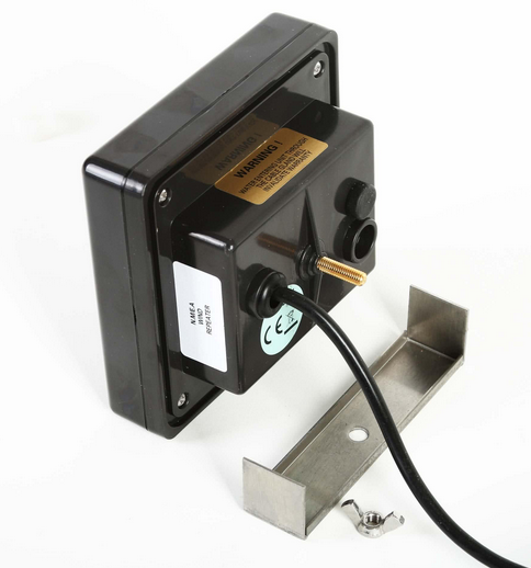
Fig .: Clipper Wind V1.0 with DIN socket (bottom right) (Clipper)
The circuit consists of a voltage converter LM7805 (IC2) for a 5V power supply for IC1 and two comparators located in an LM358N (IC1). The supply voltage for the circuit is taken from the NASA / Clipper wind instrument (pin 2 and 4). The 5V TTL data signal T + from pin 3 is fed to the comparator IC1A and compared with a 1V reference signal that is generated via the voltage divider R6 and R7. Signals from T + that are greater than 1V are recognized as a high signal and a 5V signal is output at A +, which can drive approx. 20mA to the load. This amplified signal is fed to the second comparator IC1B, which outputs an inverted signal at A-, which can also drive approx. 20mA to the load. This generates the two differential signals A + and A- for RS422.
The newer version V2.0 from Clipper Wind no longer has a DIN socket and the pin assignment is slightly different. The upper circuit can also be used for the newer version.
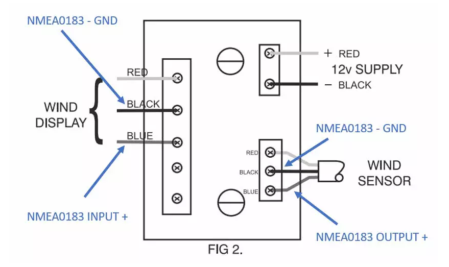
Fig .: NMEA0183 connections for Clipper Wind V2.0 (Clipper)
The circuit can be built on a breadboard and housed in a small housing. With the circuit, both the main display and the subsidiary display can be operated at the same time, and the transmitted signals can be fed into SignalK via an RS422-USB converter, for example.
A somewhat simpler circuit for an RS232 interface can also be found on the Internet. Depending on the RS232-USB converter used, the circuit may or may not work. Safe functioning is not always given and depends on the RS232 chip used, as some chips can also process signals that are not RS232 compliant. The disadvantage of this simple circuit, however, is that a daughter display cannot be operated at the same time, since the output driver in the main unit does not supply enough power.
Here is another interesting project where the NMEA0183 telegrams can be used via WiFi with a Wemos D1 mini:
https://hackaday.io/project/12986-nasa-wind-decoder