First of all, a few important notes that you should definitely pay attention to.
![]()
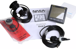
Fig.: NASA/Clipper Duet Sonar/Log
This article is about how to convert a NASA/Clipper Duet echo sounder/log so that the device outputs NMEA2000 data. This document is based on the DIY project by Sönke and was supplemented with some additional information. The NASA/Clipper Duet echo sounder/log is actually a device without a bus connection and works independently with two separate sensors. An ultrasonic sensor measures the water depth and a paddle wheel measures the speed through the water. The sensors are each connected to the display unit via a coaxial cable. The NASA/Clipper Duet echo sounder/log is widely used due to its attractive price and is used in many boats.
Table of contents
Technical specifications
The measuring device has the following properties:
- Assembly dimensions: 110 x 110 x 27 mm
- Installation depth: 40 mm
- Backlit LCD display
- 4 buttons covered with foil
- Housing ABS, black
- White top cap
- IP65 on the front
- Supply: 12V / 100mA
- Length of encoder cable: 6.5 m
- Depth measuring range: approx. 0.8...100 m
- Speed range: approx. 0…50 knots
- depth transducer
- Thread Ø: 16 mm
- Head Ø: 38 mm
- Length: 104mm
- loggers
- Thread Ø: 42 mm
- Head Ø: 70 mm
- Length: 118mm
In general, there are no technical data in the original documentation contain. Please note that the information is only a rough guide. Somehow it is completely incomprehensible that the manufacturer does not provide any technical data.
electronics
The electronics of the NASA/Clipper Duet are showing their age. It's from the 90's. An LCD is used as the display, whose segments are controlled by a display controller HT1621 be controlled. The 8-bit microcontroller is used as the central evaluation unit PIC16C63A -20/SP used with a clock frequency of 5 MHz. In addition to the main board on which the display, the microcontroller and part of the analogue electronics are located, there is another analogue board for controlling and evaluating the sensor signals. The PIC interacts with the analog board and calculates the measured values from the analog signals and controls the display controller via an SPI interface.
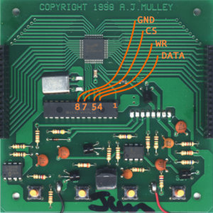
Fig.: NASA/Clipper Duet motherboard
operating principle
The basic idea of the conversion is that the SPI data signals are picked up at the SPI interface between the microcontroller and the LCD controller and evaluated with an ESP32 and output as NMEA2000 telegrams via the CAN bus.
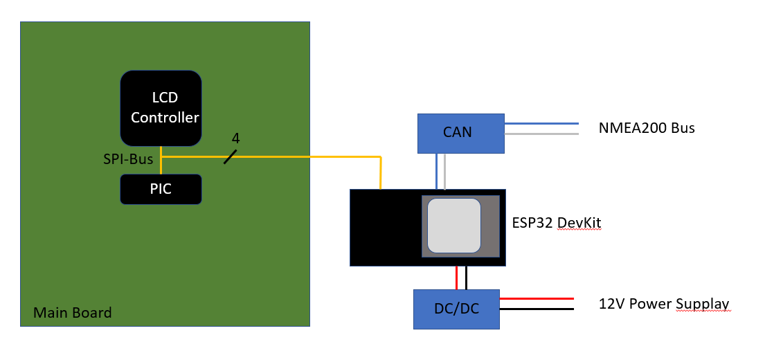
Fig.: Block diagram
The Clipper Duet's PIC microcontroller tells the HT1621 LCD controller which segments should be on depending on the values to be displayed. The diagram below shows an example of a signal curve over time on the SPI bus.
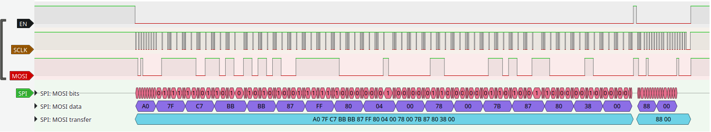
Fig.: Typical signal course on the SPI bus
The segment/com lines were examined by writing test software that causes the LCD controller to highlight individual segments so that a map of the segments and common planes could be created.
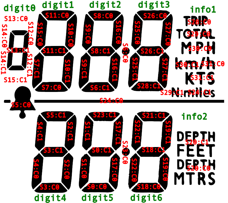
Fig.: Allocation of the segment/com lines
The ESP32 continuously analyzes the communication on the SPI bus between the PIC microcontroller and the HT1621 display controller. The PIC controller periodically sends data for the entire display memory of the LCD controller depending on the measured values. The ESP32 remaps this display memory to the 7 digits plus some symbols. The values, units and status of the Clipper Duet are then derived from the digits and symbols. The compiled data is translated into standard NMEA2000 sentences and output on the CAN bus.
Shallow depth and speed alarm settings are also read, but as there is no known NMEA2000 PGN, no telegram with these values is sent on the CAN bus.
Conversion to NMEA2000 output
The following parts are required for the conversion:
The ESP32 is used in the form of the ESP32 DevKit. This is an easy to use module with a USB port for programming. Other ESP32 modules can also be used. However, the correct pin assignment must then be observed. The easiest way is to solder wires directly to the back panel PIC microcontroller pins and connect to the ESP32 DevKit. The assignment below shows which connections must be made to the PIC controller.
Attention: It is not known whether there are different hardware revisions of the Clipper Duet. Check if you have the same TH1621 type LCD controller and same LCD layout.
Fig.: Wire connections for data tapping
| PIC controller pin | ESP32 DevKit pin | meaning |
| 4 | D12 | GPIO12, SPI MOSI |
| 5 | D14 | GPIO14, SPI CLK |
| 7 | D27 | GPIO27, SPI CS |
| 8 | GND | GND |
The following connection is established with the CAN driver module:
| CAN driver |
ESP32 DevKit pin | meaning |
| VCC | 3V3 | 3.3V |
| CAN RX | D4 | GPIO4, RXD |
| CAN TX | D5 | GPIO5,TXD |
| GND | GND | GND |
The ESP32 can only handle 3.3V on the GPIO pins mentioned above. Experience has shown that there is a tolerance of 5 V at the inputs, so that no level converters are used in view of the low cost of the ESP32 module. However, an additional power supply for the ESP32 is required. Most ESP32 modules require either 3.3V or 5V. The Clipper Duet's onboard 5V regulator should not be used as the ESP32 could draw too much current even without WIFI. A separate DC/DC converter from 12V to 5V is required.
The DC/DC converter is connected to the ESP32 DevKit as follows:
| DC/DC converter output |
ESP32 DevKit pin | meaning |
| +5V (Out+) | VIN | 5.0V |
| GND (Out) | GND | GND |
In any case, make sure to set the DC/DC converter to 5.0V on the adjustment screw before using the converter on the ESP32 DevKit. Otherwise the ESP32 can be destroyed.

Fig.: ESP32 DevKit pinout
circuit
Only a few connecting lines are required for the circuit. The circuit can easily be built on a breadboard.
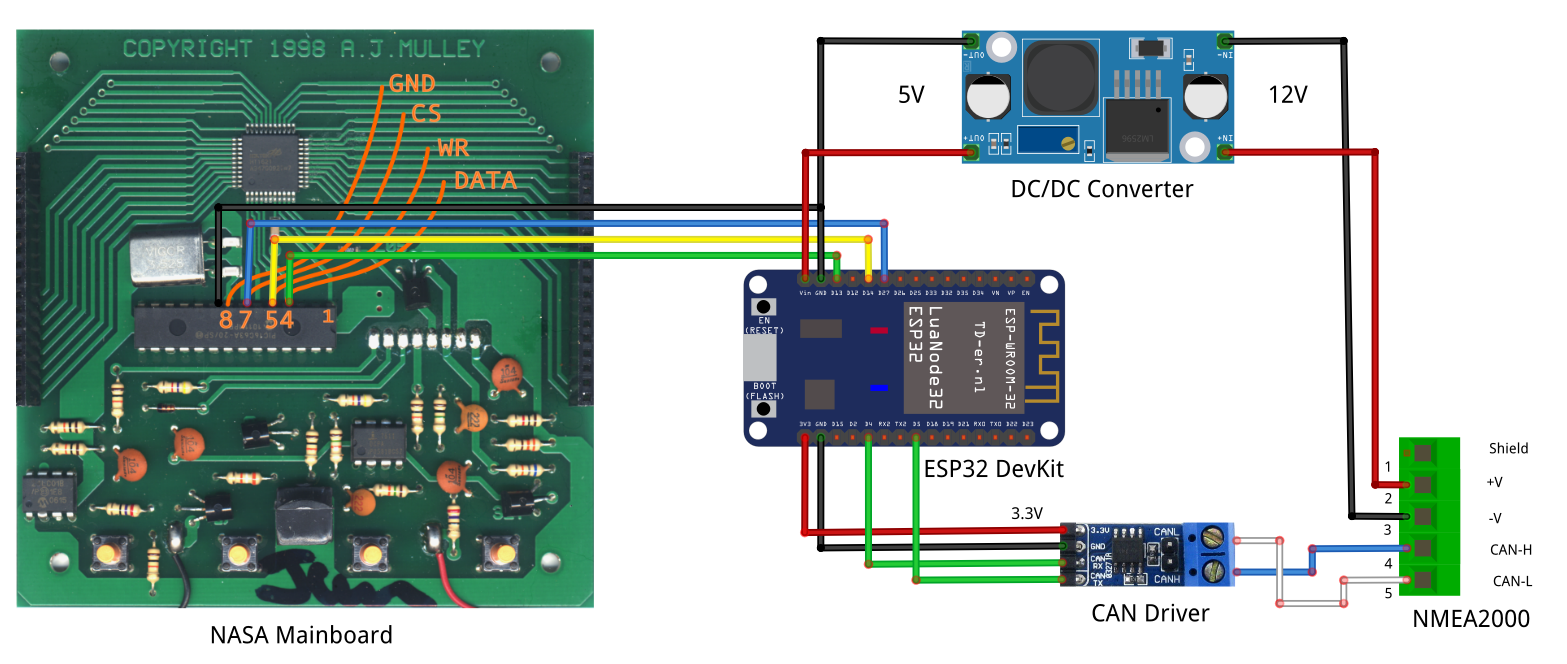
Fig.: Circuit, note! Pin 4 goes to GPIO12 of the ESP32
programming
The NMEA2000 firmware can be found in the GitHub repository: