 |

Table of contents
why
I've always found the idea of not only showing the course on my plotter when the boat is moving, but also when it's bobbing along quietly, I've always found it exciting.
After searching the I-Net for different manufacturers, it quickly became clear that I might not need an e-compass on board at current prices. Due to the corona restrictions and the more free time being spent at home, the idea of building the compass myself came up.
Der Bau des elektronischen Kompasses mit einem Ausgang in das NMEA2000 Netzwerk wurde inspiriert durch einen Beitrag von Andreas in dem „segeln-forum.de“ Forum.
Thanks to many tips in different forums, it was successful. The compass is ready, but not yet tested on the boat (status: 2022.01).
description
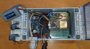
Magnetix is an electronic compass that transmits its data on the MNEA2k bus. A CMPS14 serves as a basis as a sensor, an ESP32 as a calculator, a Waveshare SN65HVD230 (don't forget to break out the resistor) as a link to the bus and an LM2596 as a voltage converter. A 0.91 inch OLED with 132×32 pixels is used for the display in the housing.
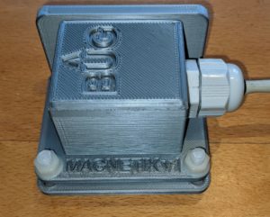
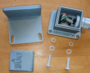
The housing for the electronics is a Bocube from "www.bopla.de". Both the bracket and the housing were 3D printed for the sensor. The brackets for the OLED and the touch sensors (VA screws) were also created with a 3 printer.
The connection between the compass sensor and the ESP is made via a KAT5 network cable, in which two cables are always connected to form a pair. Although the protocol between the CMPS and the ESP is a short range protocol (I2C), I have no problems with a cable length of ~70cm
Power is supplied via the NMEA bus and is ~1LEN. A built-in plug from Techno-Spark is used to connect to the network.
The ESP gets the data via the I2C bus, converts the whole thing into an NMEA2K data set (127250) and sends it to the network.
The compass identifies itself on the bus as "Magnetix Alpha" and can also be found under that name in the network's sources.
variables in the code
| Complete source code | https://open-boat-projects.org/wp-content/uploads/2022/01/compass_NMEA2k_V05_01.zip |
| https://open-boat-projects.org/wp-content/uploads/2022/07/compass_NMEA2k_V05_02.zip | |
devotion [] |
is an array with 36 possible entries. A deviation table can be stored in it, which automatically corrects the given course for the respective courses. |
CorrectionMountingAngle |
This can be used to set a - horizontal - correction for a deviation of the compass line from the boat axis.
[-] Values for a port correction [+] Values for a starboard correction |
service
Operation is limited to the two touch surfaces (screws):
| touch surface | function |
| 1 | Autocalibration on / off |
| 2 | |
| 1 & 2 | initiate new calibration |
screen
The display is divided into three areas:
| Left (in 90° rotated font) | |||
| Current function of the sensor | |||
| "calib" | the sensor is currently being calibrated, which was triggered by touch 1&2. | ||
| "inacc" | if the sensor is not fully calibrated (not all sensor responses are 1) “inaccurate” will appear. The HDM data was not switched off, as messages 0 occur very often.
It may have to be adjusted after field tests on board |
||
| "ON" | The sensor is in "autocalibration" mode | ||
| OFF | The "autocalibration" mode is switched off | ||
| center | |||
| S | Sensor system status followed by two numbers | ||
| A. | 'Status of the accelerometer | ||
| M | Magnetic sensor status | ||
| The three details are each specified by the following numbers: | |||
| 00 | nothing is OK | ||
| 11 | everything OK | ||
| 01 | or 10 partially OK | ||
| (Unfortunately, what these numbers mean exactly is not clear from the documentation of the CMPS14) | |||
| Right of the line | |||
| M | Magnetischer Kurs (nach dem Druck auf T2 erscheint für 2sec. „…stored…“ [v5.02]) | ||
| R | roll of the sensor | ||
| P | pitch of the sensor | ||
construction and assembly
I built the whole thing in a standard housing in which I built a base plate as a support for the perforated plate and the voltage converter. The only thing to note when assembling is that the terminating resistor on the CAN module (Waveshare SN65HVD230) has to be broken out. Otherwise the Waveshare SN65HVD230 terminates the entire NMEA bus. The wiring can be in the Circuit diagram to be checked.
Leider habe ich in der ersten Version meine Halterungen für das Display und die Touchflächen bündig an die Oberkante des Gehäuses gesetzt. Da der Deckel sich aber komplett über das untere Gehäuse „stülpt“ ging er nicht mehr zu. 🙁
updates
| 2022-03-01 | New bracket for the case with a wall bracket to compensate for a wrong horizontal installation -> Thingiverse |
| 2022-07-02 | After some testing I noticed that the sensor starts again from zero after a power loss (despite having saved the calibration). I have now changed the touch surfaces so that T2 saves the previously performed calibration. After the first tests with a restart of Magnetix it seems to be working now. (V5.02) |
libraries
the libraries used appear in the header of the INO file and are not discussed further here.
Links and Materials
gallery
 |
 |
 |