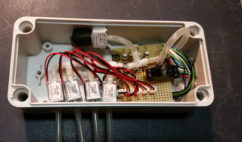
Fig. Control box with pump, pressure sensor and valves
In the Facebook group Raspberry Pi for Boats I saw a cool solution for level measurement. Erik from Finland constructed a monitoring system for 4 tanks with an air pressure sensor. The functional principle is based on the displacement of liquids in a measuring tube. A corresponding air pressure then builds up in the measuring tube, which is proportional to the level. The system uses a pump that builds up pressure in a hose system until the air flows out at the end of the hose in the tank. Depending on the length of the hose, the pump works for between 5 and 10 seconds, after which the static pressure in the hose system is measured, which is proportional to the static pressure of a column of liquid. So that you can control 4 tanks, 5 valves are built into the system, which establish a connection to the respective tank from which you want to determine the fill level. With this cool solution, he circumvents the problem of pressure loss in the hose system, because before each measurement he briefly starts the pump and refills the air that has escaped. At that time I had also experimented with hose systems and considered the solution to be unusable because I could not compensate for the pressure loss. The problem was that air has a very low density and can diffuse through hoses or escape at hose connectors. The air pressure can then not be maintained for several days or weeks. You can get around this by using continuous metal lines without connectors, which then makes the whole thing more complex. At the time I was involved in my project Engine diagnosis decided to install the pressure sensor directly in the tank and measure the liquid column directly.
Erik's solution has the advantage that there are no dangerous voltages on the tank and, in principle, you can monitor any number of tanks with the method. He uses a Raspberry Pi as an evaluation unit and displays the measurement results on a website. He housed all the electronics on a simple strip circuit board. Erik has the project on his Homepage described.
You can find one in the sailing forum interesting discussion with further information on this topic.
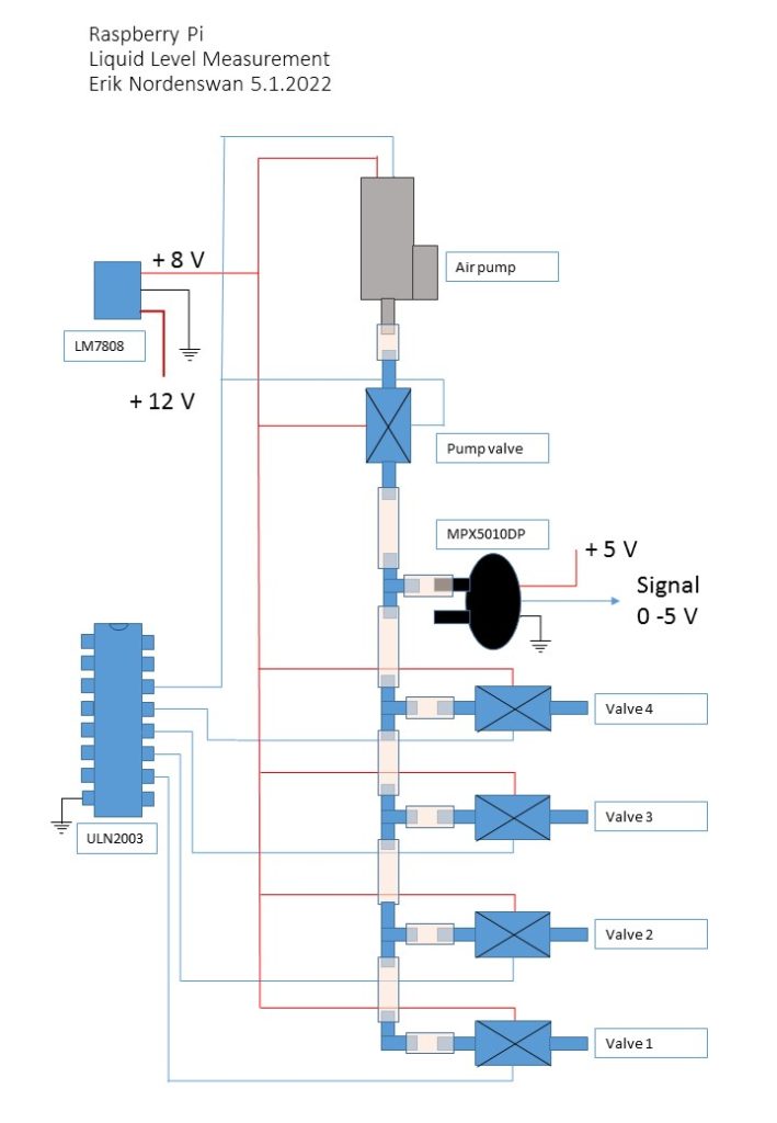
Fig. Pneumatic system structure
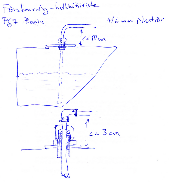
Fig. Hose end in the tank
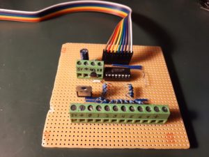
Fig. Pump and valve control
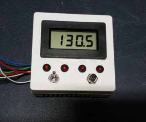
Fig. Display and control unit