Video https://youtu.be/0G_1A66hpyE
Video used as voltage input with limit alarm: https://youtu.be/XZPPG5St0Ko
https://www.segeln-forum.de/thread/79394-instrumentendisplay-diy/
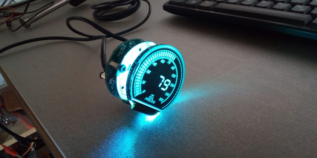
Standard built-in instruments with a diameter of 52mm are often used to display various measured values on boats. Often these can only be used for very special tasks with very special sensors. Unfortunately, the display layout differs for each task and there is no consistent appearance. While looking for a modifiable display, I came across a built-in instrument for an oil pressure display of 0… 150 psi. This display fulfills a number of requirements for a universal display:
- Digital display
- Bargraph
- Warning when limit value is exceeded
- Backlight
- 12V operation
- Analog signal input for sensors
The display has the following properties:
- 10… 15V power supply
- 1.2W power consumption
- 3x 7-segment displays without decimal point
- 2x special symbols (alarm, peak)
- 50 bar graph elements
- Buzzer for alarms
- Sensor input 0… 200 Ohm
- Button for peak reset and for configuration
The display can be parameterized in various ways:
- Background color
- brightness
- Limit values (alarm, peak)
- Type of peak display (fixed with manual reset, slow running after 1s)
- Type of bar graph control (column, single element, inverse single element)
- Buzzer volume
- Start sequence
The instrument display has the charm that you can do some things quite universally with it if you modify it a little. Without modification the following would be possible:
- Oil pressure gauge (who needs it)
- Level display 0… 100% (tank, water, standard encoder 0… 180 Ohm)
And with modification:
- Voltage display 0… 15 V
- Temperature display 0… 150 ° C
- Speed 0 ... 15 kn
- Depth 0… 150 m
- Wind direction (graphically via bar graph)
- Speed 0… 3000 rpm (with multiplier 20)
- Cooling water flow 0… 15 l / min
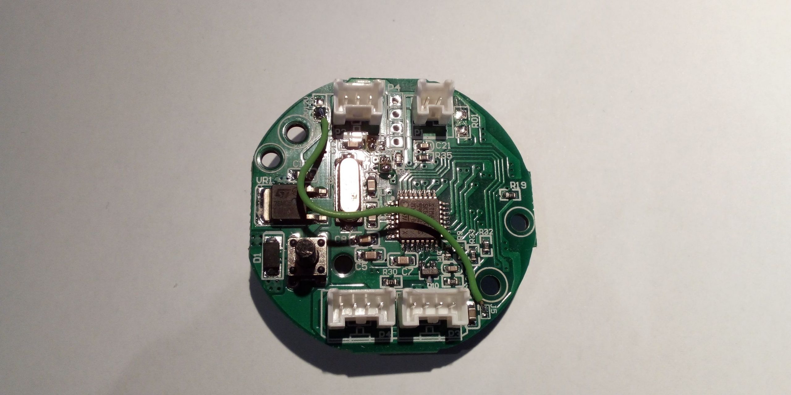
I disassembled the part and checked what was installed there. To do this, I had to bend open the black aluminum front frame from behind and remove it from the display housing. If you do it carefully, you can reattach the front frame later and continue to use it. The simplest microcontroller technology is built into the display itself:
- STM8 8-bit microcontroller
- HT1621B LCD driver
- 8 RGB LEDs as background lighting
- 7805 voltage regulator
- Customized VA LCD display (black background, transparent segments)
- 5V buzzer
The microcontroller processes 0…5V voltage signals at the analog input AIN3, with only 0…2.5V being used as the actual useful signal. This corresponds to 0…1001 ohms of the display value (or 0…200 ohms from the sensor). Voltages greater than 4.6V are detected as a faulty sensor signal and “- – -” appears instead of the numbers. There is a point on the board where you can feed in your own sensor signal 0…2.5V when the sensor is not connected. The ground reference is GND of the supply voltage. For your own applications you would therefore have to generate a voltage signal 0…2.5V that is proportional to the measured value. The sensor signal could be recorded with an ESP8266, for example, and passed on to the display as an analog output value. With a bit of ingenuity you can even fit it all into the same housing. It would also be conceivable to print your own housing that is a bit longer at the back and could accommodate the additional electronics. If you think a little further, you could also send any measured values from SignalK to the display via WLAN and show them on the screen. Using a suitable cover or a black permanent marker you could mask out the unnecessary elements so that they are no longer visible. You could also add new labels to the cover. EasyESP would be the ideal candidate for a software connection to SignalK, as there is almost finished software for this.
If you buy such a display, you have to be careful to buy the right one. The display is offered in different versions. With other versions, the modification must look different. I have currently seen the following variants:
Oil pressure 0… 150 psi (version used)
Oil pressure 0 ... 100 psi
Voltage 8 ... 18V
Tube charging pressure -30 ... + 30 psi
Notes on modification
The analog input for measuring the sensor voltage is pin 13 (AIN3) of the STM8 microcontroller. The input voltage signal can be picked up on the upper pad of JP5. Pin 1 is not used on the 3-pin sensor connector. The signal from pin 1 can be picked up on the lower pad on the adjacent, non-built-in resistor RV12V. With a cable from RV12V to J5, an input voltage of a sensor signal (0… 5V) can be fed to the analog input (AIN3) of the microcontroller. When soldering the cable, care must be taken not to short-circuit the pads with solder.
Cable bridge to sensor input P2
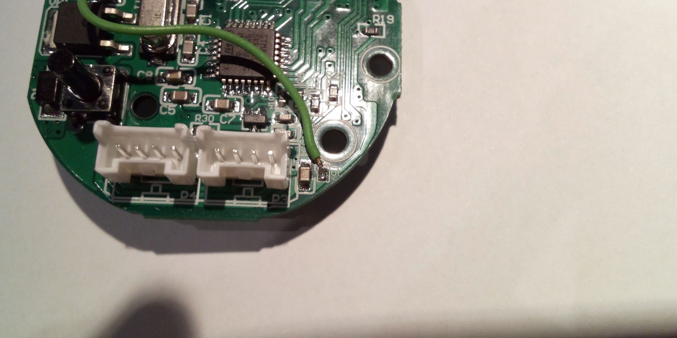
Signal feed to JP5 upper pad
The sensor cable can still be used. You only need to put the red cable on the free pin. To do this, you lift the small plastic tongue with a needle and pull the cable out to the back. The cable then automatically locks into place in the adjacent pin when it is pushed in.
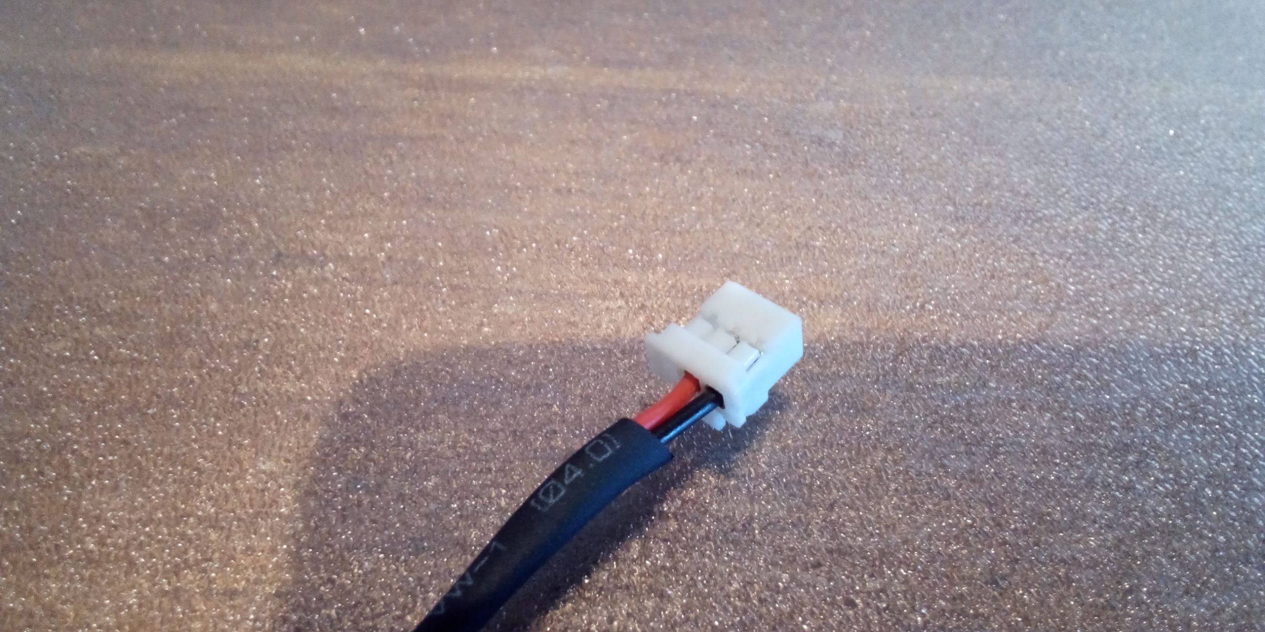
Sensor cable before the conversion
Terminal assignment
Sensor input P2 unmodified (top left)
| Pin code | colour | meaning |
| 1 | unused | |
| 2 | red | Sensor signal (0 ... 200 Ohm) |
| 3 | black | GND |
Modified sensor input P2 (top left)
| Pin code | colour | meaning |
| 1 | red | Sensor signal (0 ... 2.5V) |
| 2 | Sensor signal (0 ... 200 Ohm) | |
| 3 | black | GND |
Push button input P1 (top right)
| Pin code | colour | meaning |
| 1 | black | GND |
| 2 | red | Button |
Power supply P4 / P3 (bottom left / right)
| Pin code | colour | meaning |
| 1 | black | GND |
| 2 | yellow | lighting |
| 3 | White | ignition |
| 4 | red | + 12V |
Installation
For commissioning, the red, yellow and white cables must be connected to + 12V and the black cable to GND. P3 or P4 can be used equally. An additional display can be supplied with power with an enclosed bridge cable. Alternatively, the red and yellow cables can be permanently connected to + 12V and the black to GND. When the white wire (ignition) is then connected to + 12V, the display comes on. Before that it is in stand-by and consumes approx. 10 mA. All settings made via the button are not lost after a complete power cut-off.
Further considerations
Since the display and processing unit are basically separate, the green circuit board with the STM8 could also be replaced by a dedicated circuit board with an ESP8266. The display chip HT1621B, the lighting and the buzzer can be controlled via the connector JP1. The only problem is to find out which segments of the LCD display are assigned to which bit in the HT1621B. However, this should be quite easy to do with a test program that controls all segments one after the other. The advantage of having your own circuit board would be that you then have it in your own hands how to control the display and which values are displayed.
Theoretically, you could also have an LCD built in China according to your own requirements. For a pure LCD display, no more than 5 ... 10 euros are called for small quantities. Basically, the display is almost perfect except for the missing decimal point and the representation of the unit. Theoretically, you could also remove the fixed numbers and the lower name in the display and replace them with bright areas. Then you could create panels with transparent laser-printed plastic films with which the light areas are covered again. So you could design the display very flexibly and create new scales and labels. Unfortunately, the scale and the lettering below are not just printed elements of the display. Then you could have easily removed the labels afterwards. As a manufacturer, Bezel uses different LCD glasses for its various instruments, which are adapted to the special tasks.
More pictures

Open instrument display
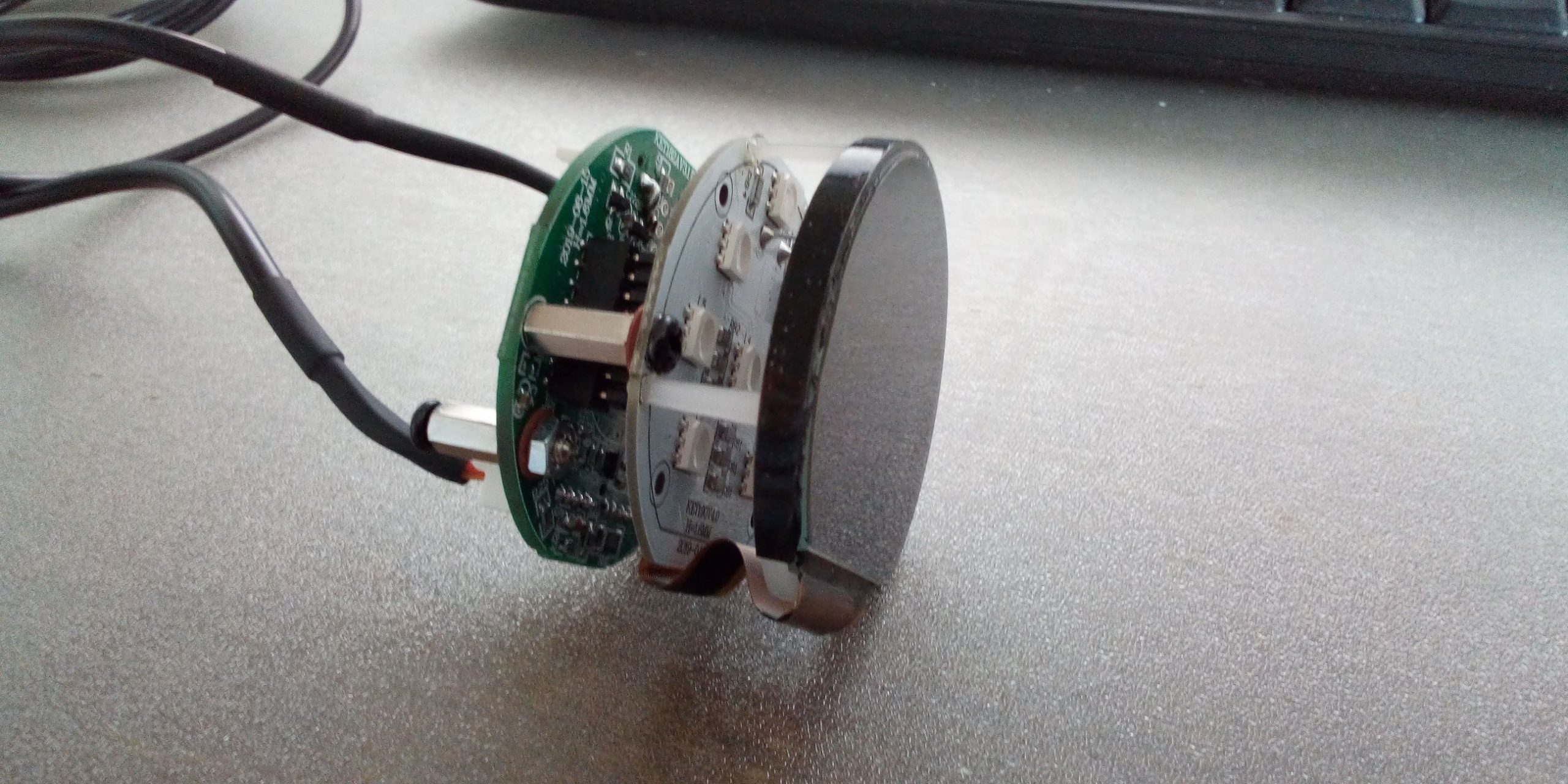
Electronics stack
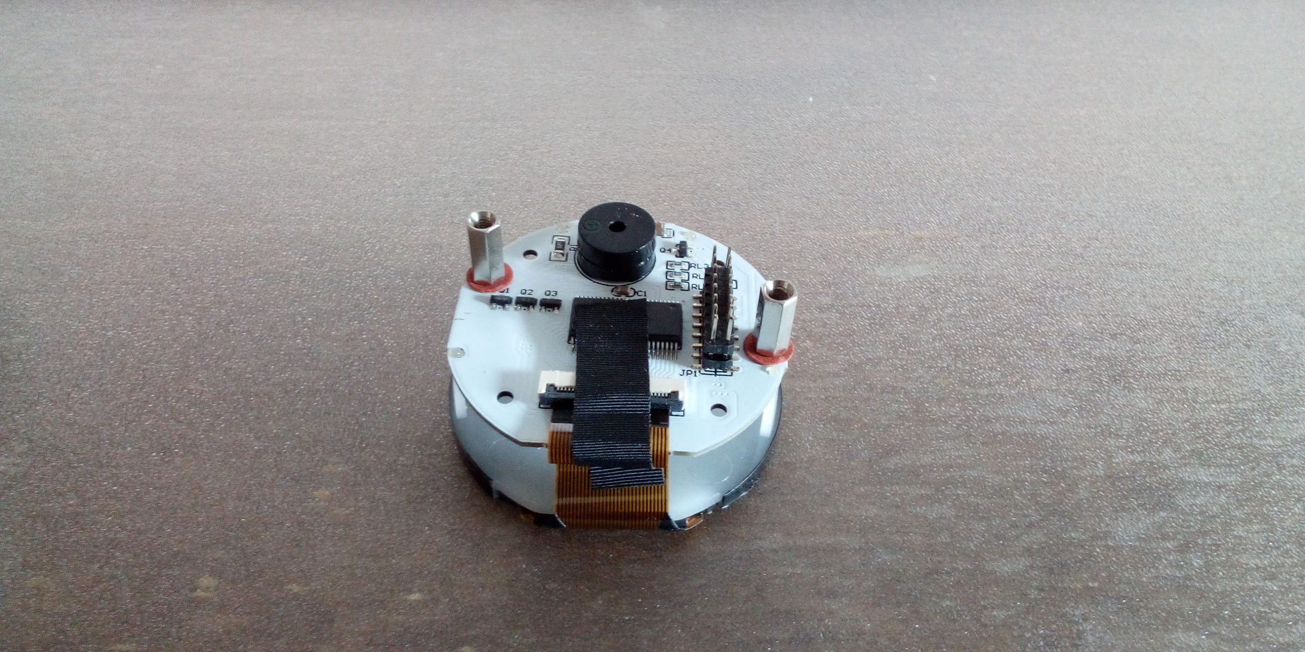
Display control board
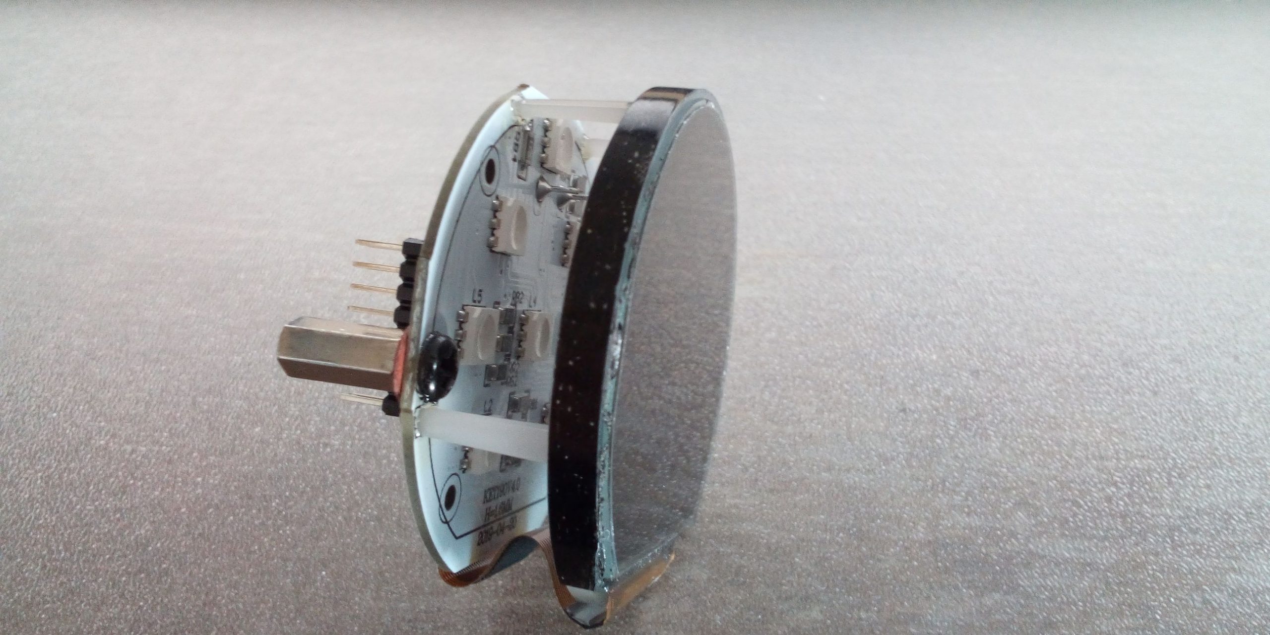
Display with display control

Strip conductor to the display
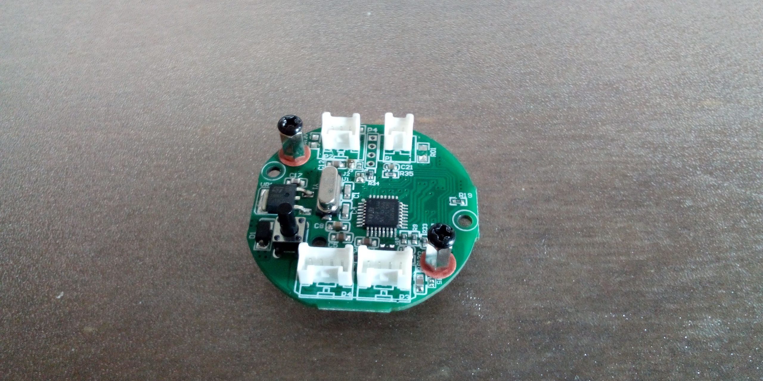
Measurement and control board in front
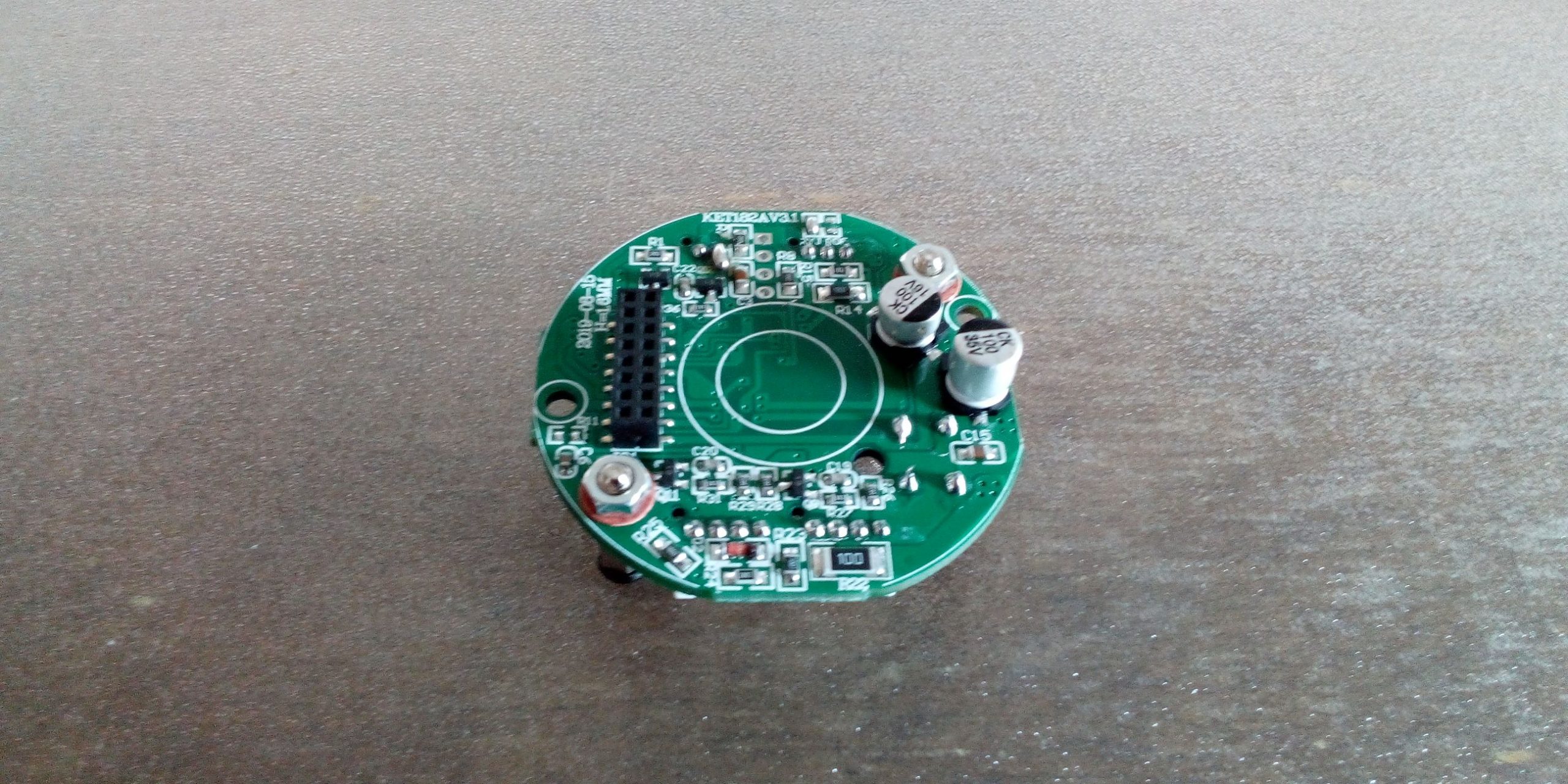
Measurement and control board at the rear
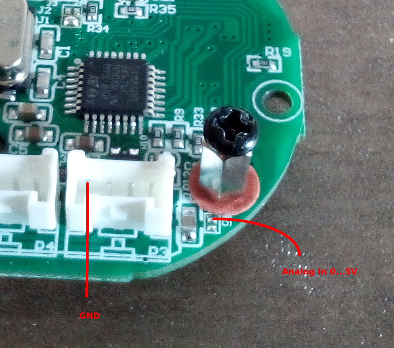
Inputs for measuring signal 0… 2.5V