Udo found an interesting AIS receiver module for us that can be used to receive AIS signals. The data is output from the GNS5851 as an NMEA0183 data stream via a serial interface.
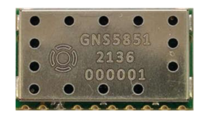
Fig: GNS5851 AIS receiver (gns-electronics.de)
The AIS receiver module GNS5851 has the following technical properties:
- Standard AIS NMEA1083 data stream
- Frequency: 161.95 to 162.05MHz
- Channels A, B or A & B (hopping)
- UART: 8N1, 115200 baud
- Sensitivity -117dBm
- Antenna Impedance: 50 ohms
- Supply voltage : 3.3V
- Power consumption : 20mA
- Logic level: 3.3V
- Temperature range: -40…80°C
- Shock resistant up to 50g
- Dimensions 26 x 15 x 3.3mm
The exact technical data can be found here: GNS5851-AIS-receiver-datasheet_0.91
The AIS receiver consists of an HF receiving unit, an AIS decoder and a CPU for data processing and communication. The module is very compact and contains all the important components for receiving AIS signals. You only need a power supply, an AIS antenna and can receive the NMEA telegrams of the AIS signals via a serial interface.
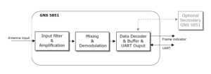
Fig: Block diagram (gns-electronics.de)
The module can be controlled via 10 pins:
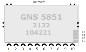
Fig. Pin arrangement (gns-electronics.de)
| Pin code | meaning | I/O | description |
| 1 | RF GND | ANT-G | antenna ground |
| 2 | RF input | ANTI | antenna input |
| 3 | GND | G | Dimensions |
| 4 | VDD | P | Power supply 3.3V |
| 5 | F_IND | O | frame indicator |
| 6 | RESET | I | Reset input (low active) |
| unused | |||
| 8 | unused | ||
| 9 | UART TX | O | TX transmit NMEA0183 |
| 10 | UART RX | I | RX receiving |
| 11 | unused | ||
| 12 | unused | ||
| 13 | unused | ||
| 14 | unused |
Tab. Pin assignment
Table of contents
Circuit example with ESP32
The connection of the GNS5851 AIS receiver is very easy, since only a few connections are required. Since the ESP32 still has enough power reserves left, the following functions have been included in the circuit:
- Measurement of the 12V board supply voltage
- Temperature measurement with DS18B20
- Buzzer for alarm signal
- NMEA2000 CAN line driver
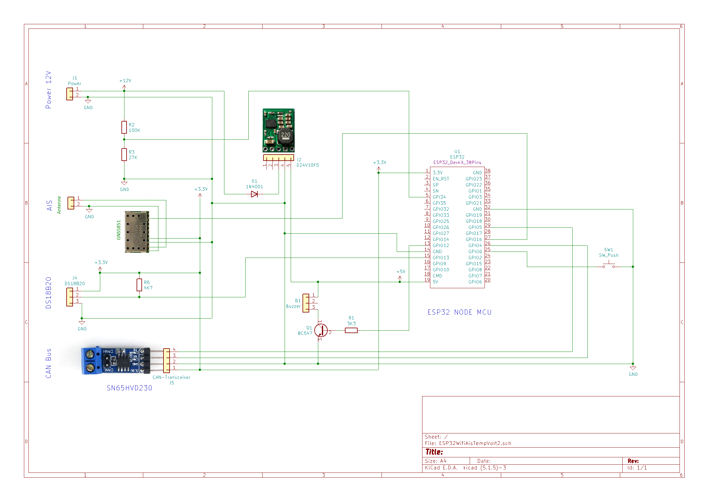
Fig: AIS receiver circuit
software
In his workshop series, Andreas Koritnik has a project for a NMEA0183 to NMEA2000 AIS Gateway created for the ESP32. Originally, the AIS-NMEA0183 telegrams were read in via an RS422 interface. In our case, the transmit output pin 9 of the GNS5851 is connected to the serial receive pin GPIO16 of the ESP32. The software can then also be used for the GNS5851. Like the finished one Binary file for the GNS5851 Loaded into the ESP32 is described in detail on the project page.
casing
Udo also kindly provided CAD files for a case that you can see in the zip file finds.
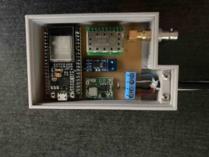
Fig. Open housing AIS receiver
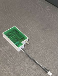
Fig. Finished AIS receiver
antenna
An AIS antenna can be set up very easily by yourself. You only need a few materials that can be easily processed. The idea came from Andreas Heger and became one of his website AIS emergency backup antenna removed.
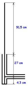
Fig: Antenna structure
The lower part of the antenna (27 + 4.3 cm) consists of a piece of RG213 antenna cable. At a distance of 4.3 cm, the shield is cut open in the RG123 cable and a cable outlet (feed line) is attached to the side. At the lower end of the antenna cable, the inner conductor and the outer braided shield are electrically connected to each other. The lower part with the antenna cable then forms a quarter-wave matching line. A 91.5 cm long rod is then soldered to the upper end of the antenna cable. Andreas used a 10 mm copper tube as a rod. This is of course also possible and is much more stable. He ended up putting everything together in a plastic tube to weatherproof it. Theoretically, the antenna could also be made from a single long piece of RG213 antenna cable by removing the braided shield in the upper part. However, you then have to think about how to mechanically stabilize the flexible inner conductor of the upper part.