First of all, a few important notes that you should definitely pay attention to.

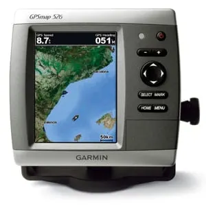
Fig.: Garmin GPSmap 526 (Garmin)
Depending on the model, older Garmin devices from the GPSmap series have one or two interfaces for NMEA0183 to enable data exchange with other devices. The article shows how to use a serial/USB adapter in conjunction with a matching circuit on a Raspberry Pi to exchange data with a Gramin device.
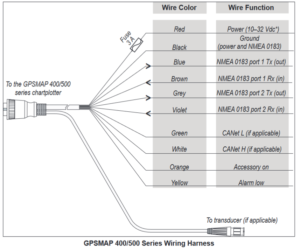
The interface signals for devices of the GPSmap 400/500 series are shown in the following figure as an example.

Fig.: Connection cable GPSmap 400/500 series (Garmin)
However, the built-in interfaces do not correspond to the RS422 standard, so that the signals from devices from other manufacturers cannot be processed. The interfaces are based on 5V TTL signals, which are also inverted. Of course, this means that communication with the usual interfaces from other manufacturers cannot work. By reengineering the interface, it turned out that the interfaces have the following technical specification:
- Communication type: Serial, 8N1, RS232-like
- Signal level: 5V TTL, inverted
- Unipolar data transmission
- Reference potential: GND
- Duplex mode (send and receive at the same time)
- Speed: 4800 bds NMEA standard (above NMEA high speed switchable to 38400Bd if AIS signals are to be processed)
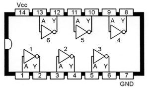
This results in the need to invert the signals. This can be done with a simple logic module 74HC04. This chip has 6 inverters, of which we need two. One for the RX signal (receive) and one for the TX signal (send). That was it already.

Fig.: Pin assignment and functional diagram 74HC04
USB serial converter for connecting to the Raspberry Pi
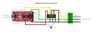
There is often a desire to enable data exchange between the Garmin device and a Raspberry Pi with AVnav or OpenPlotter. There are simple USB-serial converters that can be used for this. The wiring can be seen below.
Fig.: USB serial converter circuit diagram
The USB serial converter is first set to 5V TTL signals. There is a small jumper on the right side near the pin header. The function of the circuit is quite simple. The supply voltage for the 74HC04 comes from the PC via the USB interface. The voltage is connected to the corresponding pins 7 (GND) and 14 (+5V). The transmit signal TX Port1 from the Garmin arrives at pin 13 of the 74HC04 and is output again inverted at pin 12. The signal comes to the RX input of the USB serial converter. Conversely, this also applies to the TX signals of the USB serial converter. The TX output signal goes on pin1 of the 74HC04 and comes out inverted on pin2 and is routed to the contact strip. The inputs of all unused inverters are connected to GND so that they cannot accept undefined signals. A small 100nF capacitor protects the supply voltage of the 74HC04.
A USB cable with a mini USB connector that is no longer so common can be used on the USB-to-serial converter. On the Raspberry Pi side, the interface speed must be set to 4800 Bd. In the Garmin device, the interface is on NMEA standard placed. When using NMEA high speed a higher speed of 38400 Bd is required for AIS.
Danger! At the low speeds of 4800 Bd, you have to be careful not to send too much data in too short a time, because the interface speed doesn't always allow for this. A character is transmitted with approx. 10 bits. With 4800 Bd you can therefore transmit a maximum of 480 characters per second. They come together quite quickly with a few longer GPS telegrams, if some other data should be added.
To receive the data, an NMEA data channel is opened under AVnav or OpenPlotter via the USB interface (/dev/ttyUSBx). After that, the data can be used.
