NAVTEX is used to transmit information to seafarers and is part of the Global Maritime Distress Safety Systems (GMDSS). The information is divided worldwide by sea area and transmits current weather information as well as critical situations caused by weather and other disturbances. An example of a NAVTEX transmission from the Pinneberg transmitter in Germany is shown below:
<10/18/2025 09:55:12> ZCZC LE71 180950 NAVTEX-HAMBURG (NCC) FORECAST GERMAN BALTIC COAST UNTIL 10/19/2025 06 UTC: FLENSBURG TO FEHMARN: NW 4-5, MODERATE VISIBILITY IN AREAS AT NIGHT. EAST OF FEHMARN TO RUEGEN: W-NW 4-5, MODERATE VISIBILITY IN AREAS AT NIGHT. BODDEN WATERS EAST AND EAST OF RUEGEN: WESTWARD WINDS 4-5, MODERATE VISIBILITY AT NIGHT. NNNN ----------------------------------------------------------------------- <18.10.2025 09:54:09> ZCZC LA27 NCC-HAMBURG 281230 UTC SEP 25 NAUT. WARNING NO. 485 WESTERN BALTIC SEA. NORTH OF FEHMARN. BUOY 'W2' 54-33.7N 011-06.8E MISSING. NNNN ----------------------------------------------------------------------- Extract: NAVTEX message dated 18.10.2025, Station Pinneberg
NAVTEX transmissions are made according to the SITOR-B (AMOTOR) Procedure on two longwave frequencies in the lower sideband:
- 490kHz – Broadcasts in national language (related to broadcast region)
- 518kHz – Broadcast in English
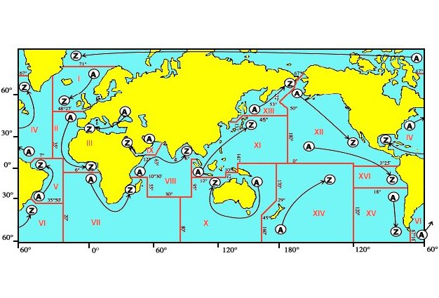
Fig.: Division of the sea areas into different regions (Wikipedia)
There are 160 transmitting stations worldwide that broadcast NAVTEX messages. Within a region, the transmitters have identifiers from A to Z, and each station covers a sea area between 150 and 559 nm. The transmitters in all regions are positioned to provide almost complete coverage of the geographic region and major maritime trade routes.
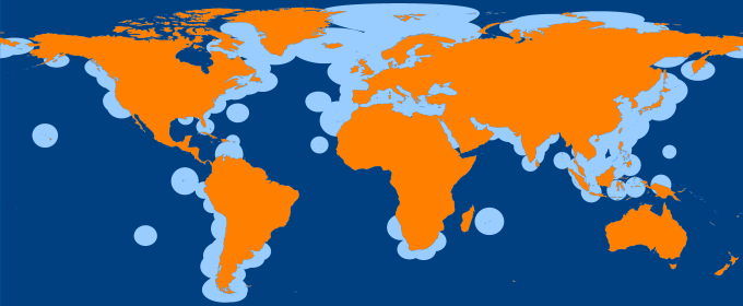
Fig.: Coverage of regions (Siranah)
To avoid mutual interference, the stations follow a fixed transmission schedule. Within a region, only one station transmits at a time. Broadcasting schedule always begins with station A and ends with station Z. A station's transmission window is 10 minutes, and a further transmission occurs after 10 minutes from the next station in the alphabet. This prevents other stations from interfering with each other's transmissions on the same frequency. This enables globally standardized NAVTEX receivers that only need to evaluate two fixed frequencies and can be used in all regions of the world.
Table of contents
SSB modulation
The following shows how the signal of a NAVTEX transmitter is composed and why the lower sideband is used for transmissions. This information is taken from the website frisnit.com and are reproduced here in a revised form.
For data transmission, electromagnetic waves with a fundamental frequency are used as carriers, which are amplitude-modulated. An amplitude-modulated RF signal is shown below. The carrier frequency has the frequency fc and the amplitude-modulated useful signal has the frequency fm.
A carrier wave modulated to 100 % with a tone results in the waveform and spectrum shown below:

Where y= sin(f c )*(sin(f m )+1)
Most of the transmitter's output power flows into the carrier (center peak), which carries no information. This can be suppressed at the transmitter by removing the bias from the modulation signal:
y = sin(f c )*sin(f m )
Only the two sidebands remain at f c +f m and f c -f m left over :

This improved the efficiency of the transmitter, but it still required twice as much power through the two sidebands as actually needed. The identical wanted signal is present in both sidebands. The upper sideband (USB) or the lower sideband (LSB) can be removed while retaining the channel's wanted data signal. This is better explained by looking at a diagram of an SSB modulator. If the lower sideband is suppressed, the following signal is obtained.

The single-side band signal (SSB signal f ssb ) can be obtained by mixing with the output of a local oscillator operating at the same frequency as the carrier f c of the transmitter. This results in two frequency components, one at f c +f ssb and the other at f c -f ssb which contains the desired information. The higher of the two values can easily be removed by filtering, as it is usually much higher than the desired signal. The graph below shows the result. Only the desired signal is visible on the spectrum, since f c +f ssb outside the right end of the display.

Any discrepancy between the frequency of the receiver's local oscillator and the transmitter's carrier causes the spectrum of the received signal to be shifted by the amount of the error. With speech signals, this can make the speaker sound like Donald Duck. Another problem with SSB is that you may not know whether the wanted signals are being transmitted in the USB or LSB. Therefore, you don't know which side of the carrier signal to set the local oscillator to. If you get it wrong, the spectrum of the received signal will be inverted. Speech will then be distorted and unintelligible.
The following diagram only makes sense if you include the system diagram of an SSB modulator above. It shows the output of an SSB transmitter with incomplete carrier suppression. Sometimes a residual carrier frequency is intentionally transmitted to provide the receiver with a reference signal to tune into.

NAVTEX data format
NAVTEX messages are sent in SITOR-B (AMTOR) format that CCIR 476-character set is used. This character set is arranged so that each 7-bit character contains 4 ones and 3 zeros for error detection. This limitation reduces the number of characters that can be accommodated in 7 bits, so two character sets must be used. The receiver switches between them. The control character FIGS signals that the numeric character set should be used and LTRSthat the alphabetic character set is selected. Below you will find tables of the two character sets.
Alphabetical character set
|
|
0 |
1 |
2 |
3 |
4 |
5 |
6 |
7 |
8 |
9 |
A. |
B. |
C |
D |
AND |
F |
|
0 |
|
|
|
|
|
|
|
|
|
|
|
|
|
|
|
ALPHA |
|
1 |
|
|
|
|
|
|
|
J |
|
|
|
F |
|
C |
K |
|
|
2 |
|
|
|
|
|
|
|
IN |
|
|
|
AND |
|
P |
Q |
|
|
3 |
|
|
|
BETA |
|
G |
FIGS |
|
|
M |
X |
|
In |
|
|
|
|
4 |
|
|
|
|
|
|
|
A. |
|
|
|
S |
|
I |
IN |
|
|
5 |
|
|
|
D |
|
R |
AND |
|
|
N |
LTRS |
|
SP |
|
|
|
|
6 |
|
|
|
WITH |
|
L |
REP |
|
|
H |
|
CH32 |
|
LF |
|
|
|
7 |
|
THE |
B. |
|
T |
|
|
|
CR |
|
|
|
|
|
|
|
Numeric character set
|
0 |
1 |
2 |
3 |
4 |
5 |
6 |
7 |
8 |
9 |
A. |
B. |
C |
D |
AND |
F |
|
|
0 |
|
|
|
|
|
|
|
|
|
|
|
|
|
|
|
ALPHA |
|
1 |
|
|
|
|
|
|
|
\ |
|
|
|
! |
|
: |
( |
|
|
2 |
|
|
|
|
|
|
|
2 |
|
|
|
6 |
|
0 |
1 |
|
|
3 |
|
|
|
BETA |
|
and |
FIGS |
|
|
. |
/ |
|
= |
|
|
|
|
4 |
|
|
|
|
|
|
|
– |
|
|
|
BEL |
|
8 |
7 |
|
|
5 |
|
|
|
$ |
|
4 |
3 |
|
|
, |
LTRS |
|
SP |
|
|
|
|
6 |
|
|
|
+ |
|
) |
REP |
|
|
# |
|
CH32 |
|
LF |
|
|
|
7 |
|
9 |
? |
|
5 |
|
|
|
CR |
|
|
|
|
|
|
|
To protect against transmission errors, each individual character is sent a second time, interleaved by three characters. Both characters must arrive intact at the receiver for the character to be displayed. Here's an example:
...ABCDEFGHI...
This is how it would be nested:
. . . ABCDEFGHI . . . . . . ABCDEFGHI . . .
This is how it is transmitted:
...ABCADBECFDGEHFIG.HI..
This coding scheme dates back to the 1960s and, due to its simplicity, is very cost-effective for transmitting and receiving devices. In practice, it works very well for this purpose. The low data rate of 100 bps promotes a low error rate even in difficult reception situations.
The interleaved transmission of the characters requires that the receiver is regularly synchronized with the transmitter to enable correct decoding. This is done by alternately transmitting the ALPHA- and BETA-character several times. These phase pairs can be heard in the generated files as regular beeps at the beginning and end of the message.
NAVTEX encoder
Frisnit.com offers a web-based NAVTEX encoder , which can be used to convert NAVTEX messages into audio signals and modulate the carrier frequency. The audio signal has a bandwidth of 2 kHz. The audio signal is output as a WAV file. If desired, noise can also be added to simulate reception interference.
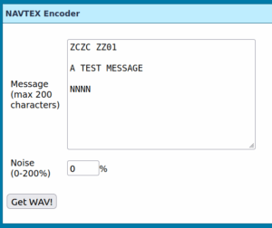
Fig.: NAVTEX encoder
Here are some generated sample files with different noise interference signals:
- navtex_0_noise.wav
- navtex_50_noise.wav
- navtex_100_noise.wav
- navtex_150_noise.wav
- navtex_200_noise.wav
Even if noise is added to the useful signals 150% as interference, the information can be received reliably.
NAVTEX decoder
Frisnit.com also offers a NAVTEX decoder software which can be used to decode lower sideband audio signals. The decoder software is available in two versions:
- NAVTEX_2.1.5, executable Windows file (WinXP, Win2000, WinNT)
- JavaNAVTEX_0.2, Java file (Linux, Mac)
The Windows file offers significantly more functionality than the Java file. Decoded signals can also be sent to the cloud, allowing you to receive current broadcasts over the internet without a NAVTEX receiver. However, this requires a free registration with Frisnit.
The software installation follows the following steps:
- Download the ZIP file.
- Create a directory and extract the file into it, maintaining the directory structure.
- Start the program by double-clicking on the file NAVTEX_2.1.5.exe for Windows or JavaNAVTEX_0.2.jar or use the command line java -jar ./JavaNAVTEX.jar.
- Select an available audio input and connect the computer's audio input to the audio source (microphone or external audio source e.g. ATS25X2)
- For 518 kHz NAVTEX, set your radio to 516 kHz USB and the NAVTEX signal will appear in the tuning window at about 2 kHz.
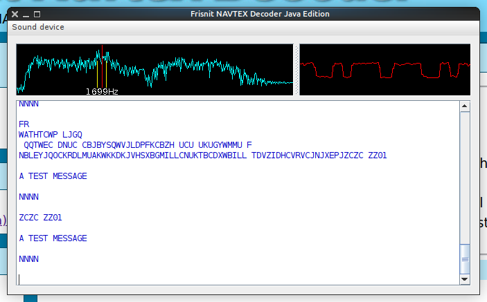
Fig.: Java NAVTEX decoder under Linux
NAVTEX data receiver ATS25 X2
The NAXTEX signals can be ATS25X2 received and can be passed to the audio input of the software decoder.
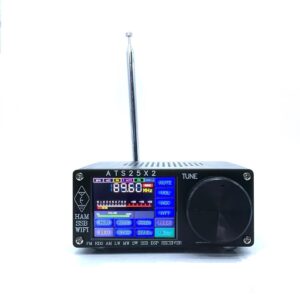
Fig.: ATX25 X2 all-range receiver
You must use a mini whip antenna to ensure a sufficient reception signal.
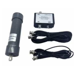
Fig.: Mini-whip antenna
The following instructions should be observed regarding NAVTEX reception settings:
How can I receive NAVTEX with the ATS25 X2?
The NAVTEX signal tones can be received with the ATS25 X2 if there is a local Navtex station nearby fixed broadcast times The device has its own software decoder that converts the sounds into text messages. ATS25X2 The analog audio signals can be output via the headphone output and decoded by external software.
How do I have to set up the ATS25 X2 to be able to receive Navtex?
Navtex is broadcast at 518 kHz in the upper sideband (USB) in the Sitor-B. The center frequency is 1700 Hz +/-170 Hz frequency shift. The transmission speed is 100 Bd. The ATS25 X2 is set to 516 kHz with BFO -625 Hz and USB with a filter width of 2.2 KHz. Once the tones have been found, the filter width can be reduced to 1 kHz and the BFO is slightly configured to optimally hear the two tones.
Which Navtex frequency should I use?
The Navtex information is in individual regions in the world divided up. On 518kHz Messages are always sent out in English. The reports in the regional language, however, are published 490kHz sent out.