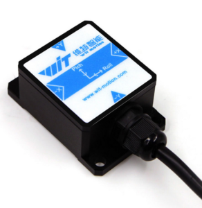
Fig.: HWT901B-RS232 9-axis sensor
The Chinese company WIT motion sells various sensor modules on the Internet. In addition to 3-axis, 6-axis and 9-axis modules, pure magnetometers are also offered in a wide variety of designs. A large number of interfaces are supported such as:
- TTL
- RS232
- Modbus
- Bluetooth
- WiFi
A particularly interesting sensor is the HWT901B-RS232. This is a 9-axis sensor as a military variant with the following properties:
- 3-axis acceleration sensor
- 3-axis gyrometer
- 3-axis magnetometer
- BMP280 environmental sensor (temperature, air pressure, humidity)
- 32Bit CPU for 9-axis sensor fusion
- Accuracy roll, pitch: 0.05°
- Accuracy heading: approx. +/-5° (1 sigma)
- 5…36V supply voltage
- 40mA power consumption
- RS232 interface 9600Bd 8N1 (adjustable)
- Kit includes a USB/serial adapter
- Binary data format (hex values)
- 1…20Hz data rate (adjustable)
- Roll, Pitch, Yawl, Heading
- long-term stable readings
- Waterproof aluminum housing IP68
- Extensive Windows configuration software (from Win7 upwards)
- Good comprehensible documentation
USB/serial adapter
To connect the HWT901B-RS232 SignalK To be able to use either a serial interface or a USB interface of the Raspi is used. The supplied USB/serial adapter is not easy to use if you use the plug contacts already attached to the sensor, as they can quickly slip off the adapter. But that is sufficient for the first test. Later on in the boat it is most helpful to solder the cables directly to the connectors of the USB/serial adapter and to protect the exposed circuit board with a large amount of shrink tubing or electrical tape against accidental short circuits. Alternatively, the adapter can also be accommodated in its own small housing.
Important: RX from sensor must be connected to TX of adapter and TX of sensor to RX of adapter.
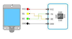
Fig.: Serial connection (Wit-Motion)
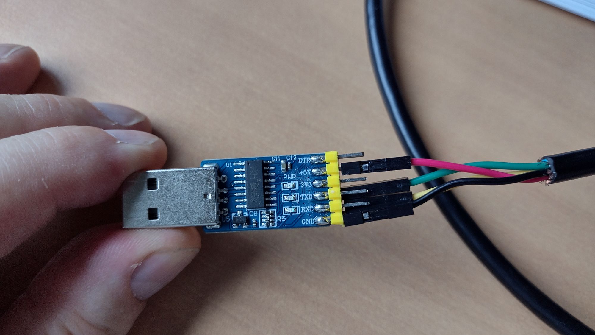
Fig.: USB/serial adapter with connectors
Fig.: Directly soldered cables
Calibration of the sensor
The HWT901B-RS232 calculates the internally with a 32-bit CPU via a sensor fusion Euler angle. In sensor fusion, the measurement data from the acceleration sensor, gyrometer and magnetometer are calculated into a set of three angles that can be used to describe the orientation of a solid body in three-dimensional space. As a result of the sensor fusion, roll, pitch and heading are output as sensor readings. In order for the sensor fusion to work correctly, all individual sensors of the HWT901B-RS232 must be calibrated. The manufacturer offers Windows configuration software for this purpose. With this software, the correction parameters of the respective sensors from the acceleration sensor, gyrometer and magnetometer in all 3 axes are determined by special movements when the sensor is removed and stored permanently in the sensor after calibration. This calibration is called initial calibration. The second step is to install the sensor in the boat. The heading offset and the deviation table are then determined in the installed state. The sensor is then fully calibrated. The initial calibration only has to be carried out once, while the determination of the deviation table always has to be carried out if the installation location of the sensor in the boat has changed or if major inaccuracies have arisen over time.
Initial calibration
For initial calibration, the sensor is removed and connected to a Windows PC via USB. After that the configuration software MiniIMU.exe called.
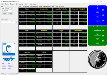
Fig.: MiniIMU
The Windows PC should be not connected to the internet otherwise the configuration software will be automatically updated in a faulty version. The calibration takes place under Config in 3 steps:
- Calibration of the acceleration sensor (in a horizontal, stable position)
- Calibration of the gyrometer (in a horizontal, steady position)
- Calibration magnetometer (in the form of 3-dimensional movements)
The acceleration sensor and the gyrometer are calibrated in a horizontal, stable position. The sensor must be aligned exactly horizontally and must not be moved. This works best on a flat tabletop. The calibration should not be carried out in the boat.
Great care must be taken when calibrating the magnetometer. In the end, negligence significantly worsens the quality of the magnetic direction value (heading). It must be ensured that there are no metal parts or interfering magnetic fields within a radius of approx. 1 meter. The sensor connection cable is quite short and must be used close to the Windows PC. Keep as far away as possible and stay away from speakers. Small loudspeakers with extremely strong magnets are built into laptops in particular, which you often don't think of. These interference fields can severely affect the calibration of the magnetometer and make it impossible. The best calibration results are obtained with the Elliptical Calibration achieved. To do this, the sensor is moved freely in the hand at a height of 50 cm from the tabletop in all 3 axes so that elliptical point clouds are created for the 3 spatial planes XY, XZ and YZ, the edges of which are sharply defined as in the picture see.
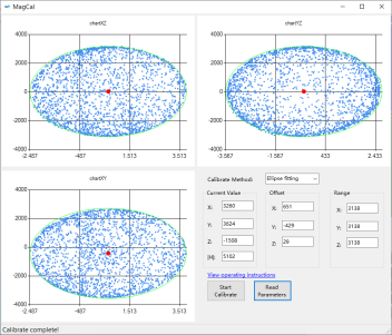
Fig. Correct calibration of the magnetometer
During calibration, the sensor always has to be rotated slightly differently in space until the edges of the ellipse are evenly marked with measuring points. The calibration progress can be monitored quite well via the live graphics. If individual measuring points appear clearly outside the edge of the ellipse, this is a sign that the calibration did not run correctly and that interference fields are present. It takes about 3 to 5 minutes to collect enough measuring points. The calibration of the magnetometer can also be repeated later in the boat if necessary. However, the calibration of the accelerometer and the gyrometer must never be carried out in the boat.
Setting the transmission format
In order for the data to be correctly recognized by the SignalK plug-in, the sensor must be set to send only angle data. Only the data set 'Angle' is used under Config activated. To be on the safe side, the plugin automatically resets this setting every time it is started. All other values are left at the default values. The default baud rate of 9600 is sufficient for up to 50 data records per second (output rate: 50Hz) and must not be changed.
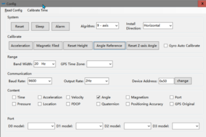
Fig.: Broadcast formats
Integration into SignalK
The sensor can easily be integrated into SignalK via the plugin signalk-hwt901b-imu include The supplied USB/serial adapter is used for this and the sensor is connected to the Raspi via USB. In the configuration of the plug-in, the appropriate USB device is selected and the desired transfer rate is set.
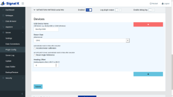
Fig.: SignalK plugin for HWT901B-RS232
The 'Return Rate' transmission rate determines how many measurements per second are to be transmitted to SignalK. The heading offset can be set to set the installation direction of the sensor in relation to the bow. The plug-in can also be used to subsequently calibrate the acceleration sensor as well as roll and pitch or to set them to zero. However, this is only advisable if the boat is in an absolutely still position.
Determination of the heading offset and the deviation table
The last step of the calibration takes place when the sensor is permanently installed in the boat. The following things should be considered during installation in order to achieve the best results:
- Place the sensor away from:
- metal parts
- power lines
- Magnetic interference fields such as loudspeakers or mechanical compasses
- Attachment in the middle of the boat
- Attachment if possible in the pivot point of the boat
- If possible, horizontal or vertical installation (no inclined installation)
An ideal installation location would be the cabin ceiling behind the mast at the ship's pivot point or on the forward bulkhead in the boat. Whether the installation location of the sensor was selected correctly can only be determined after the deviation table has been determined. The location of the sensor may have to be changed again and the calibration repeated.
The deviation table can be created in different ways. You always need a GPS receiver as a heading reference, such as a cell phone with a corresponding app that can display the heading.
The deviation table is either determined manually by driving courses in 20° steps over a distance of approx. 100m and assigning the measured value from the sensor. The boat should have a speed of at least 2…3 knots so that the GPS receiver outputs reliable heading values. The data rate from the magnetic sensor and from the GPS sensor should be identical to avoid problems with the evaluation. A data rate of 1 Hz is sufficient for data recording. In addition, the speed should be as constant as possible. The determined data can be recorded in an Excel spreadsheet and later calculated.
Another variant would be to continuously save the heading values of the sensor and the GPS receiver while driving and to subsequently calculate the recorded values in an Excel spreadsheet. To do this, you would drive the boat 2 circles to the right and 2 circles to the left. The circles should have a diameter of approx. 200 m and the speed of the boat should be constant at 2...3 knots. The data should be discarded for short, quick turns, since the GPS sensor is somewhat slower than the magnetic sensor. This method gives the best results because there are measured values for all direction values. If you use SignalK, you can activate the plugin for the InfluxDB database and have the data recorded there. With Grafana, the measurement results can then be monitored and assessed during the test drive.
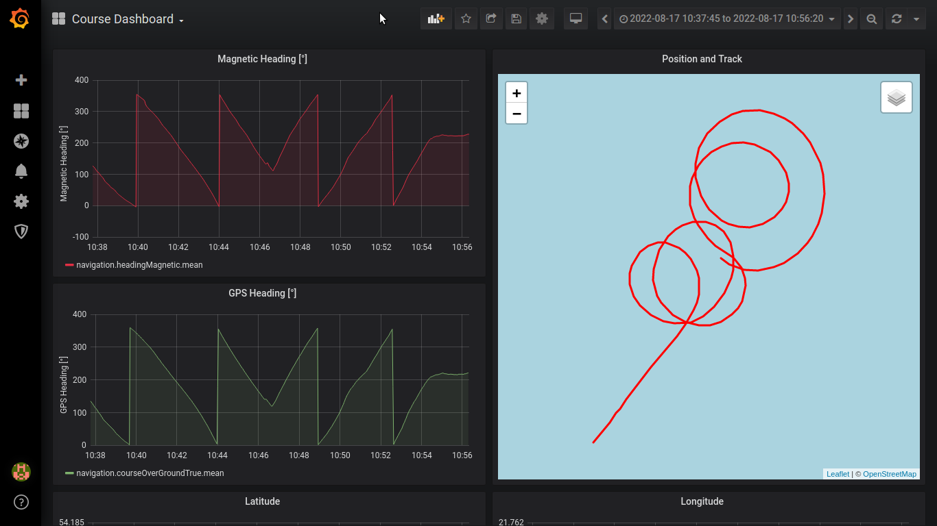
Fig.: Representation of the measured values in Grafana
At the end, the recorded values are used to create a table and a diagram in which the deviations of the magnetic sensor are plotted against the reference values from the GPS sensor. It is also very helpful to record the heading values of both sensors in a diagram.
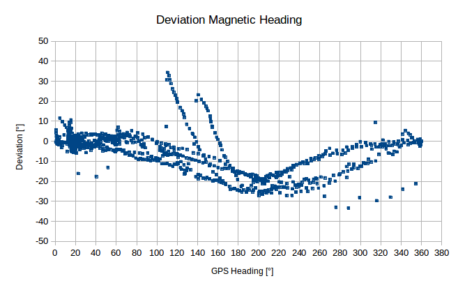
Fig.: Magnetic deviation from GPS (uncorrected)

Fig.: Magnetic compass and GPS compass heading (uncorrected)
If possible, you should get a straight line in the diagram that has no bumps. Large bumps are a sign of interference fields or metal parts around the sensor. The deviations should not be more than +/-20°. If the values are higher, a different installation location for the magnetic sensor is recommended. On steel boats it may be necessary to mount the magnetic sensor outside the hull.
heading offset
The heading offset can be seen in the following diagram. It is the angle difference across all angle values versus the GPS value. The misalignment is referred to as the heading offset and is given in values of up to +/-180°. This value is set in the plugin signalk-hwt901b-imu under Heading Offset registered.
Fig.: Heading Offset uncorrected
deviation table
In order to be able to correct the sensor raw data from the HWT901B-RS232, we use the SignalK plugin Calibration. With the plugin, any sensor values can be corrected by creating a correction table. The measured value and the value that you want to receive as the corrected value are always entered. However, it must be ensured that the values are entered as radians (multiples of PI). Degrees cannot be used because SignalK internally uses ISO units and uses all angle data as radians. Under Path In our case, the SignalK-Path for the magnetic sensor is entered. as Source WT.1 must be specified. Contrary to the plugin description, the value for Period must be left blank, otherwise the measured values will not be corrected correctly. Apparently the plugin is faulty at this point.
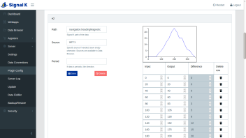
Fig.: Deviations table in the calibration plugin
Calibration check
After the HWT901B-RS232 magnetic sensor has been calibrated, the measurement results can be checked again. For this purpose, the same measured values are recorded as when determining the deviation table. The errors should be less than +/-5° at the end. If this is not the case, the complete calibration should be repeated and, if necessary, a new location for the sensor in the boat should be selected.
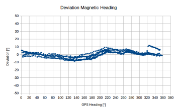
Fig.: Magnetic deviation from GPS (corrected)
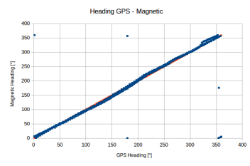
Fig.: Magnetic compass and GPS compass heading (corrected)