In boats, several devices may be connected to a marine antenna. The radio is often connected to the marine antenna in the mast, and an AIS receiver is also operated on the same antenna. For this to work, an antenna splitter is required to prevent the transmission power from coupling directly into the AIS receiver during transmission, thus preventing the AIS receiver from being damaged. Suitable splitters are available for purchase from marine suppliers. A distinction is made between passive and active splitters. Passive splitters use a specific arrangement of conductors to separate the signals. Active splitters switch off the AIS output when transmitting. These devices are quite expensive, and some users prefer to use a second AIS antenna to avoid the splitter problem.
If you look at the functional principle of the passive splitters, you will see that the structure is actually quite simple and is based on a Wilkinson divider The Wilkinson splitter isolates the two antenna outputs P2 and P3 from each other from an RF perspective through a clever arrangement of two coaxial cables with a terminating resistor. The disadvantage of the passive splitter is a signal loss of 6 dB, which is hardly noticeable in practical operation. With active splitters, this signal loss can be avoided.
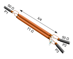
Fig.: Passive AIS splitter (Wilkinson splitter)
The concept of two coaxial cables is so simple that you can implement it as a DIY project. Anyone who can cut cables to within a millimeter should be able to create such a cable without any measuring equipment. Splinters You can build it yourself. A standard TV antenna cable can be used as the 71 ohm coaxial cable (orange). The approximate length of the two orange cables is approximately 460 mm for 162 MHz.
Caution: Common 75 ohm coaxial cables have a velocity factor of around 0.68 (see the respective data sheets for details). A lambda/4 cable would therefore only be 300 / 162 / 4 * 0.68 = 0.31 m long.
I don't think you need any measurement equipment at all for the setup if you stick to solid materials. It will work so well right away that you won't need to make any adjustments. The whole thing can also be rolled up and installed in a metal box and fitted with BNC or PL259 connectors.
In my DIY project for a AIS-Antenna It worked right away, and the frequency was perfectly matched. All they had to do was cut a coaxial cable to the correct length and insert an outlet for the antenna connection at the correct location.
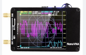
Fig.: Nano VNA
If you are unsure whether the splitter is working properly in the frequency range, you can check the setup with a high-frequency network analyzer such as the Nano VNA test. However, this requires some know-how in RF measurement technology.